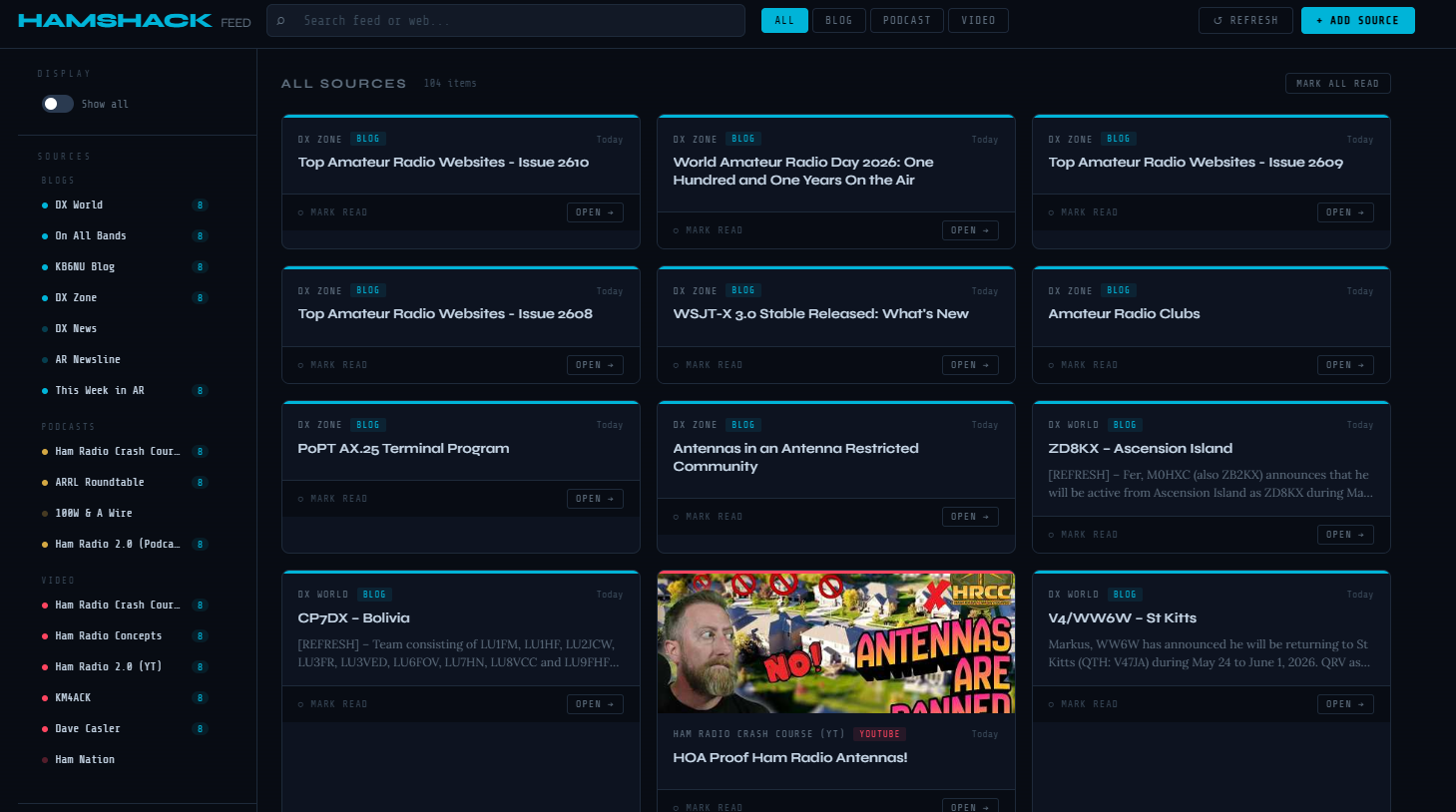
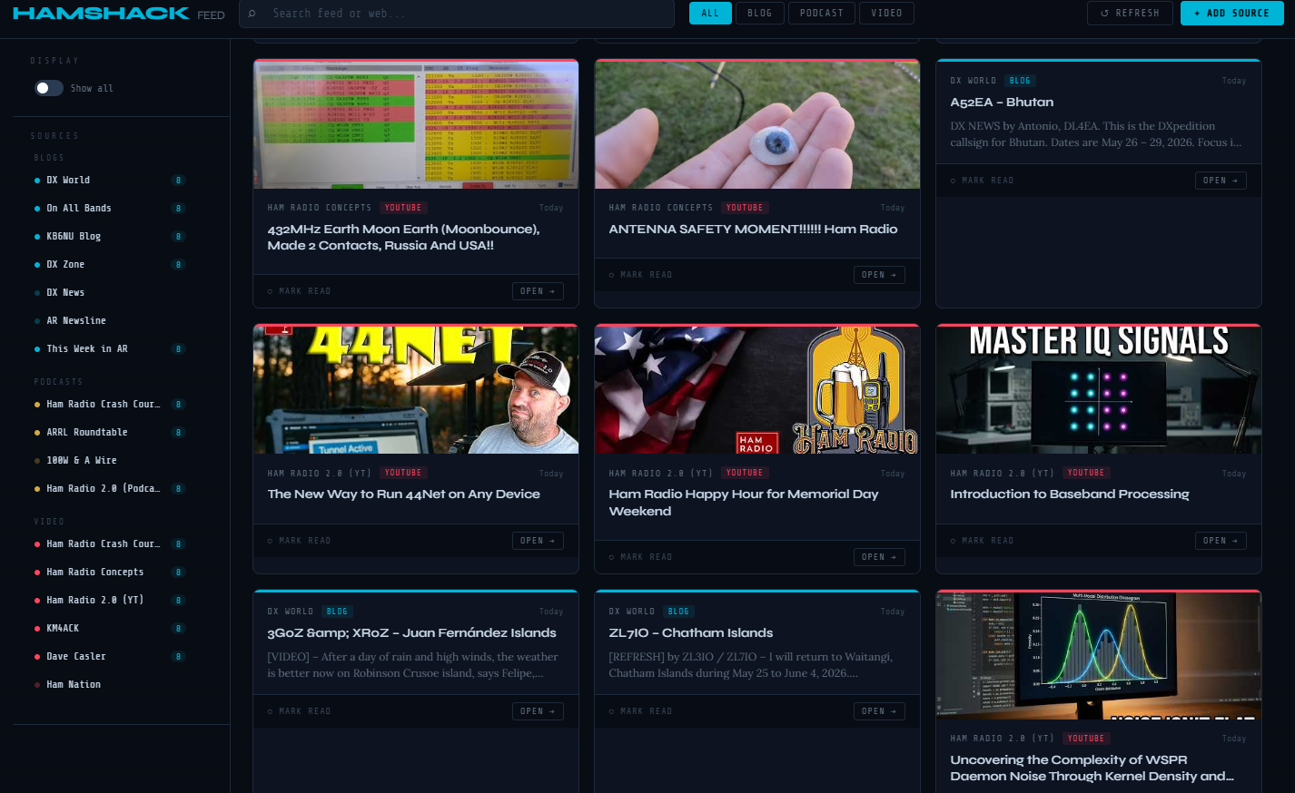
This is the final post in the Stream Deck for Ham Radio series. We’ve covered mode launchers, a live propagation dashboard with storm alerts, rotator control, and a ham radio content aggregator. This post ties it all together — how the custom icons were created, how to get started building your own setup from scratch, and some closing thoughts on how this project evolved.
Everything built in this series is available for download at the project’s GitHub repository: github.com/N4MI73/streamdeck-hamradio. A complete step-by-step setup guide is also available as a PDF download — more on that at the end of this post.
Custom Icons
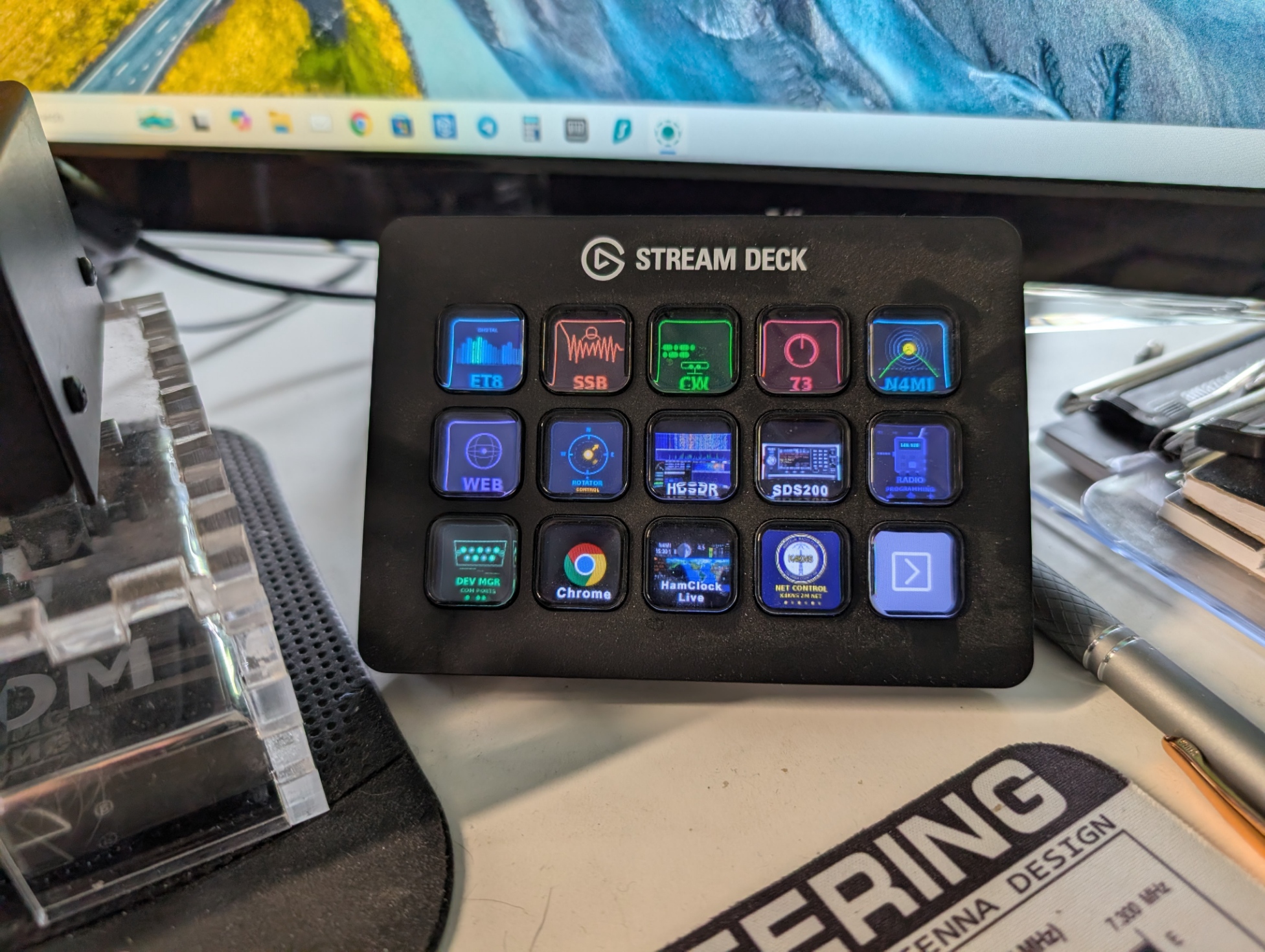
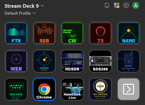
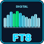
The Stream Deck’s physical buttons are small — about 15mm square — so icons need to communicate their function at a glance without any reading required. The built-in Stream Deck software includes a basic icon editor and access to a marketplace, but I wanted something more cohesive — a consistent visual language across every button that made the whole layout feel like a purpose-built tool rather than a collection of random images.
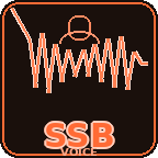
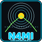
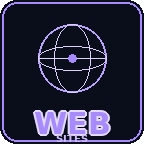
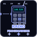
All of the custom icons in this project were generated using Python with the Pillow imaging library, with Claude helping design and write the generation scripts. Each icon is a 144×144 PNG with a dark background, rounded corners to match the physical button shape, and color coding by function — cyan for digital modes and web tools, warm tones for voice modes, red for shutdown, and compass-themed designs for the rotator controls.
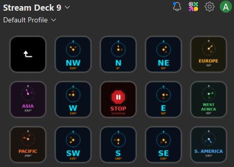
Here’s a sample of the icon set:
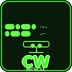
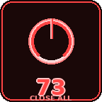
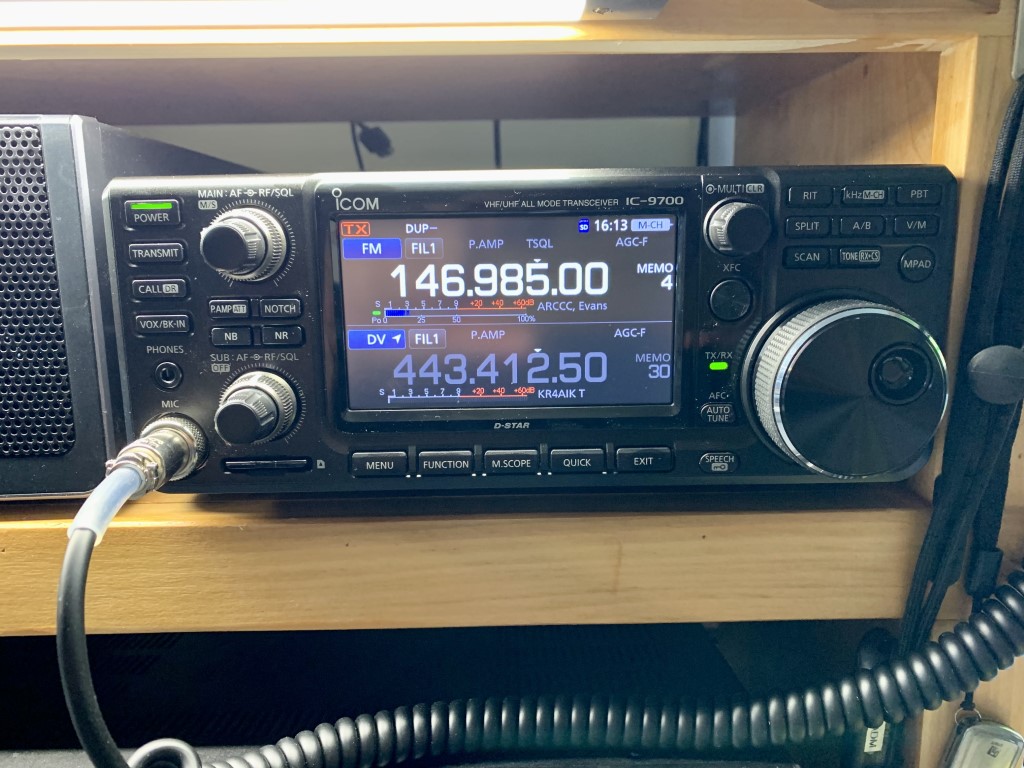
The radio programming folder contains icons for each radio in the shack — actual photos of each model used as button images, making it immediately obvious which button opens which programming software. This folder was added after the rest of the project was built, which is a good example of how the setup grows naturally over time.

The complete icon set — all 39 icons including compass directions, DX region presets, mode launchers, utility buttons, and radio programming icons — is available in the icons/ folder of the GitHub repository.
Getting Started
If this series has you interested in building your own setup, here’s the honest starting point: you don’t need to build everything at once. The most useful place to start is a single button that launches one app you open every operating session. Get that working, then add another. The full setup shown in this series grew one button at a time over several weeks.
The minimum requirements to get started:
- An Elgato Stream Deck (any model — the 15-key MK.2 is a good starting point)
- The free Stream Deck software from Elgato
- The free Advanced Launcher plugin by BarRaider from the Stream Deck Plugin Store
- Python 3.x installed with “Add to PATH” checked — only needed for the dashboard
- The scripts and files from the GitHub repository saved to
C:\Ham Scripts\
The scripts are plain text files that can be opened and edited in Notepad. The paths to your applications are set at the top of each script — update those to match your installation and everything else works as written. Claude at claude.ai can write or troubleshoot PowerShell scripts if you describe what you want — that’s exactly how all of the scripts in this project were built.
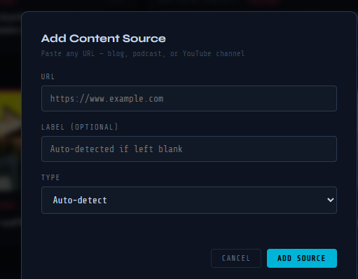
A complete step-by-step guide covering everything from finding app paths to configuring Stream Deck buttons, writing PowerShell scripts, setting up the dashboard server, and creating custom icons is available as a free PDF download:
📄 Download the Stream Deck Setup Guide (PDF)
Closing Thoughts
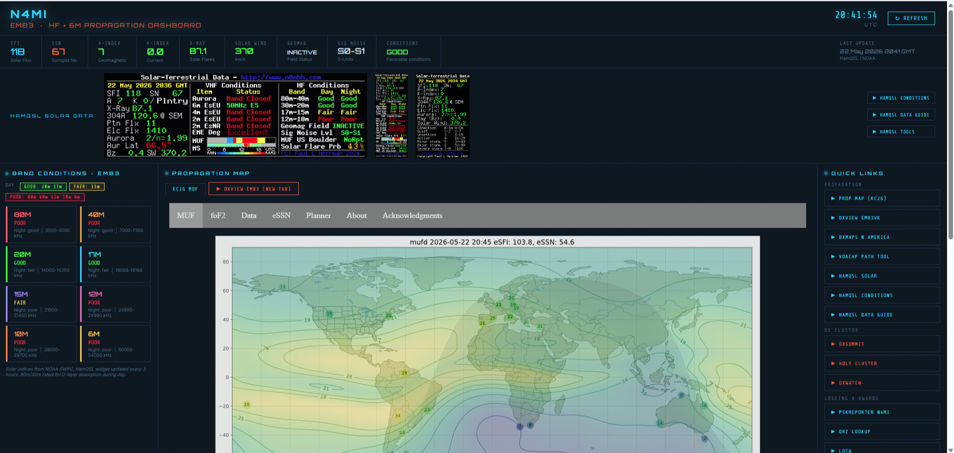
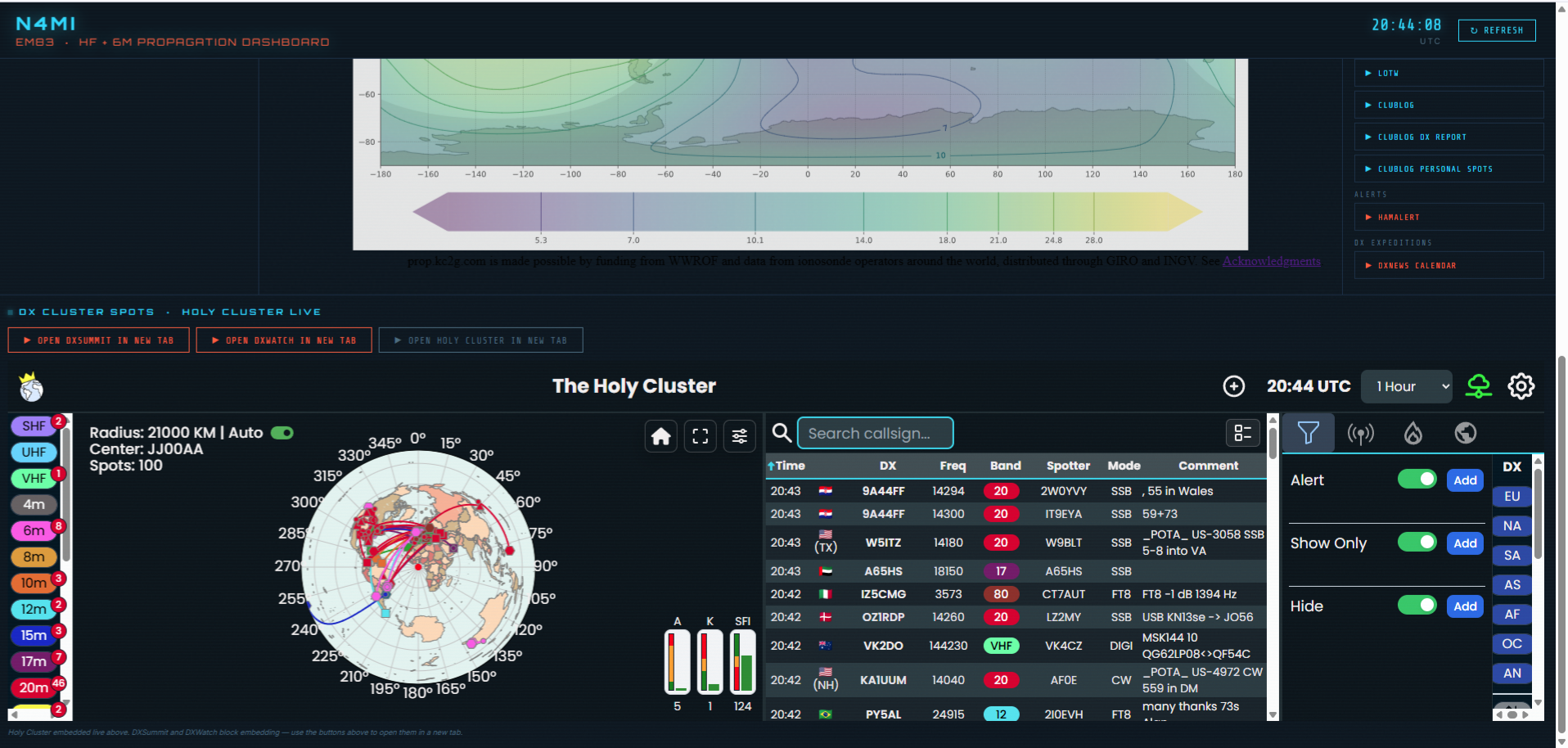
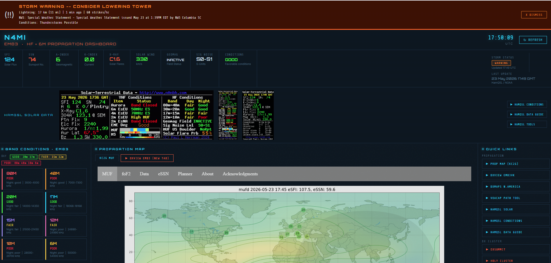
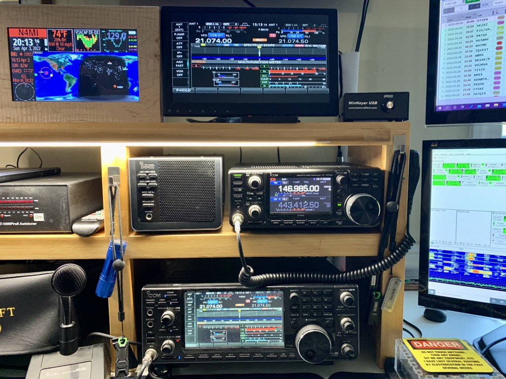
This project started with a simple goal — stop manually opening the same five apps every time I sat down to operate. It grew from there into something I use every day: mode launchers, a propagation portal, storm alerts, rotator control, a content aggregator, and a full set of custom icons. None of it was planned from the start. Each piece was added because something in the workflow felt like it could be smoother.
That’s the thing about a setup like this — it’s never really finished, and it doesn’t need to be. The Stream Deck is just a tool for running scripts, and PowerShell scripts are just text files. Adding a new button takes a few minutes. Changing how something works takes editing a few lines in Notepad. The barrier to customization is low enough that the setup can evolve naturally with your operating habits.
I’m sharing all of this as a fellow hobbyist — not for any commercial purpose, and not because my particular setup is the right one for anyone else’s shack. The scripts, dashboard, icons, and setup guide are all free to download, modify, and build upon. If you improve something, add a feature that would be useful to others, or adapt this for a different logging program or rotator controller, please share it. That’s how the ham radio community has always worked, and it’s how this kind of project gets better over time.
Thanks for following along with the series. The complete project is at github.com/N4MI73/streamdeck-hamradio. 73 de N4MI!