If you’ve been following this blog, you know I’ve been building out a suite of automation tools for my ham shack — a Stream Deck-based launcher system, a propagation dashboard, a storm alert system, and a ham radio content aggregator called HamShackFeed Pro. Each of these tools scratches a specific itch, and this one is no different.
This post introduces ManualShelf, a locally-hosted manual catalog I built to solve a problem that probably sounds familiar: I have a lot of PDF manuals, and I can never find the one I need.
The Problem
Over the years I’ve accumulated manuals for radios, antennas, accessories, logging software, digital mode programs, and more. They live in a few folders on my ham computer, organized well enough, but “well enough” stops working the moment you’re in the middle of a QSO and need to find a specific setting buried somewhere in a 180-page Icom manual.
Windows Explorer is fine for managing files, but it’s not a library. There are no thumbnails, no descriptions, no tags, and no way to search inside documents. I knew a manual existed — I just couldn’t find it fast enough.
I looked at full-featured document management systems like Paperless-NGX, which runs on my NAS and is excellent for what it does. But it’s heavyweight — it requires Docker, a database server, and a full processing pipeline. For a folder of radio manuals, that’s more infrastructure than the problem deserves.
What I wanted was something simpler: show me my manuals, let me search them, and open the right one. That’s ManualShelf.
What It Is
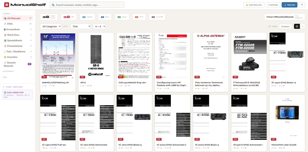
ManualShelf is a lightweight web application that runs on your own computer. You point it at your folders, it scans for supported files, generates thumbnails, and builds a searchable catalog. From then on you can browse, filter, search, and open any document in a few clicks — all from a clean browser interface at http://localhost:8075.
Everything runs locally. No cloud, no account, no subscription. Your files stay exactly where they are — ManualShelf only stores metadata (title, tags, descriptions) and thumbnails in its own small database.
How It Works
Adding Files to the Catalog
Click Add Manuals, paste in a folder path, and hit Scan. ManualShelf recursively searches the folder and everything inside it, then shows you a list of what it found. Files already in the catalog are grayed out so you don’t add duplicates. New files are pre-checked and ready to add.
Click Add Selected and ManualShelf does the rest — generating a thumbnail from the first page of each PDF, recording the file size and page count, and adding it to the catalog. You can save frequently scanned folder paths in Settings so you don’t have to retype them each time.
Finding What You Need
The search box works across title, filename, make, model, description, and tags simultaneously. But the more useful feature for a manual-heavy catalog is full-text PDF search — ManualShelf can look inside the text of your PDFs, not just their filenames. Run Re-index PDFs from the Settings menu once, and from then on a search for “AGC” or “menu 5-7” will surface the right manual even if those words aren’t in the filename.
Results that matched on text content (rather than metadata) show a small purple PDF TEXT badge so you know why they surfaced.
The sidebar lets you filter by file type, category, tags, or favorites. A tag cloud makes one-click filtering easy once you’ve tagged your files.
The Detail Panel
Click any card to open the detail panel. This is where you edit the title, add make and model information, assign a category, write a short description, and add tags. The file path, page count, and file size are shown at the top, and an Open File button launches it in your default application — Adobe Reader for PDFs, Excel for spreadsheets, and so on.
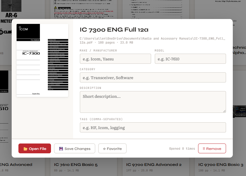
The detail panel also tracks how many times you’ve opened a file, which turns out to be a handy “most used” indicator over time.
Supported File Types
ManualShelf handles more than just PDFs. The full list:
- PDF — thumbnail from first page, full-text search indexing
- Images (PNG, JPG, GIF, BMP, WEBP) — useful for settings screenshots
- Word documents (DOCX, DOC)
- Spreadsheets (XLSX, XLS, CSV)
- PowerPoint presentations (PPTX, PPT)
- Markdown files (MD) — rendered and displayed in-app
- Plain text (TXT) — displayed in-app
- HTML files
Bulk Editing
Once you have a catalog going, you’ll want to tag and categorize things. The Select mode lets you click multiple cards and apply tags or a category to all of them at once — either replacing existing tags or merging with them. Much faster than editing each file individually.
Update Detection
When a manufacturer releases a revised manual and you drop the new version into your folder with the same filename, ManualShelf notices. Re-scanning the folder flags the changed file with an amber UPDATE badge, pre-checked for you to select. Updating it refreshes the thumbnail and file data while keeping all your metadata — title, tags, category — intact.
Settings and Cross-Computer Visibility
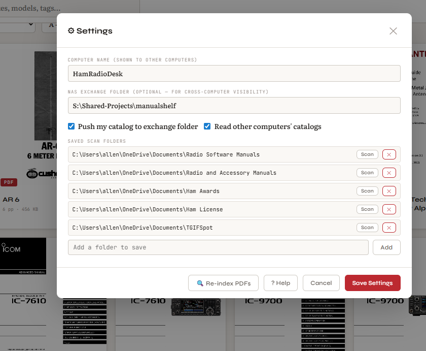
The Settings panel is where you configure a few important things. The Computer Name identifies this machine in the catalog. The NAS Exchange Folder is where ManualShelf publishes a summary of your catalog — if you run ManualShelf on a second computer pointing at the same network folder, each machine can see the other’s catalog under a Remote Manuals filter. You can browse titles, descriptions, tags, and metadata for manuals on the other computer, which is useful for knowing a document exists somewhere on your network.
I run ManualShelf on both my ham computer and my admin computer. The ham computer has radio and antenna manuals; the admin computer has more general reference documents. Both can see each other’s catalogs.
The Help System
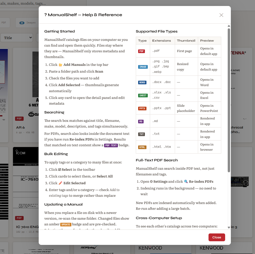
Since I wanted ManualShelf to be useful to others beyond my own shack, I built a help modal into the app — accessible via the ? button in the top right corner or from the Settings panel. It covers the full workflow, all supported file types, how full-text search works, how to use bulk editing, and the cross-computer setup process.
How It Was Built
ManualShelf is built in Python using Flask — a lightweight framework for running web applications locally. The catalog is stored in SQLite, which is a simple database format that requires no server setup; it’s just a file on disk. PDF thumbnails are generated using a library called PyMuPDF, which can read PDF files and render individual pages as images. The web interface is a single HTML file with straightforward JavaScript — no frameworks, no build process.
The whole thing is designed to be simple to install and run. If you have Python on your computer, it’s a few commands to get started.
Part of a Larger Project
ManualShelf is part of my ongoing ham shack automation project, which started with a five-part blog series about using an Elgato Stream Deck to launch radio software, control my antenna rotator, and display a propagation dashboard. Since then I’ve added a storm alert system that monitors my WeatherFlow Tempest weather station, a ham radio content aggregator called HamShackFeed Pro, and now ManualShelf.
All of these tools share the same design philosophy: run locally, no cloud dependencies, open the right thing with one button press.
Everything is available free on GitHub at github.com/N4MI73/streamdeck-hamradio, with full setup instructions in the README.
What’s Next
A few things are already on the backlog for ManualShelf — a notes field for each entry, related file linking, and a broken file detector that flags catalog entries whose files have been moved or deleted. Nothing scheduled yet, but the foundation is solid and extending it is straightforward.
If you give it a try, I’d be curious what you think. The ham radio context is just where it was born — the app is general-purpose and works just as well for any collection of documents you want to keep organized.
73, Dan — N4MI