I decided to build a small 50W VHF/UHF station to use for portable operations, such as supporting events or setting up in a temporary location, with a choice of using AC power or a battery. I don’t need anything fancy like DMR or D-Star, but I might want to to use it for APRS or WinLink.
After a bit of research and pricing options, I went with something that turned out to be a very easy build. I chose a Yaesu FTM-6000R as the transceiver. It has basic features, but has gotten some good reviews. It is also known to be a good transceiver for data, and is 9600 bps capable.
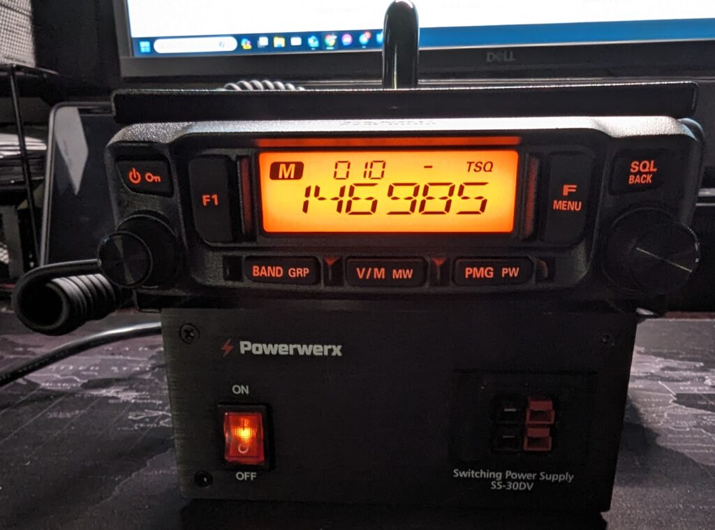
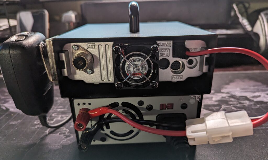
I also chose a 30 amp switching power supply and a mobile base station enclosure from PowerWerx, to make it a single unit that’s easy to carry around. The enclosure includes a short DC cable to connect the radio to the power supply. If I want to use a battery instead of the power supply, I just disconnect the T-connector from the power supply, and connect it to the battery. It was very easy to assemble the whole system.
I tested with the power supply and with a battery, and it works great. The whole unit is very compact and stable.
My next step will be to configure it for WinLink and APRS. I have a Mobilinkd TNC-4, and I ordered a DigiRig. The FTM-6000R has a 10 pin MiniDin connector, and DigiRig sells 1200 bps and 9600 bps cables for the radio. DigiRig also sells an adapter cable to use DigiRig cables with a Mobilinkd, and vice versa.
I’ll make another post after testing the setup with WinLink and APRS.
It has been a year since I posted a new item! Time to get back to it! My last post was about a project for my IC-705 using an M5Stack microcontroller. I became interested in learning about other ham radio related projects using microcontrollers.
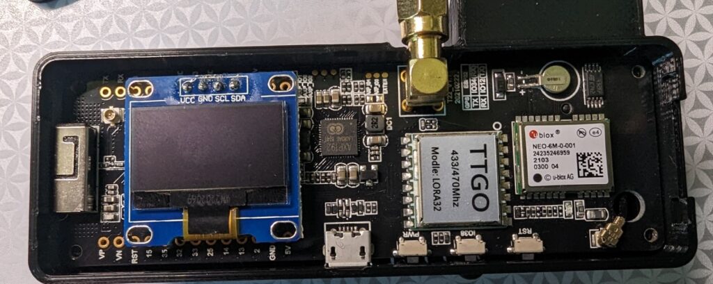
Searching online, I found two related projects to build an APRS iGate and a tracker. Both of these projects use inexpensive LoRa32 microcontroller boards. I chose TTGO T-Beam v1.1 boards that operate on 433 MHz. Make sure you buy the 433 MHz version of the board for the APRS projects. The board includes a small OLED screen, and has onboard WiFi, GPS and SMA connector for the antenna. You will probably have to solder the OLED screen to the board, but there are only four pins to solder.
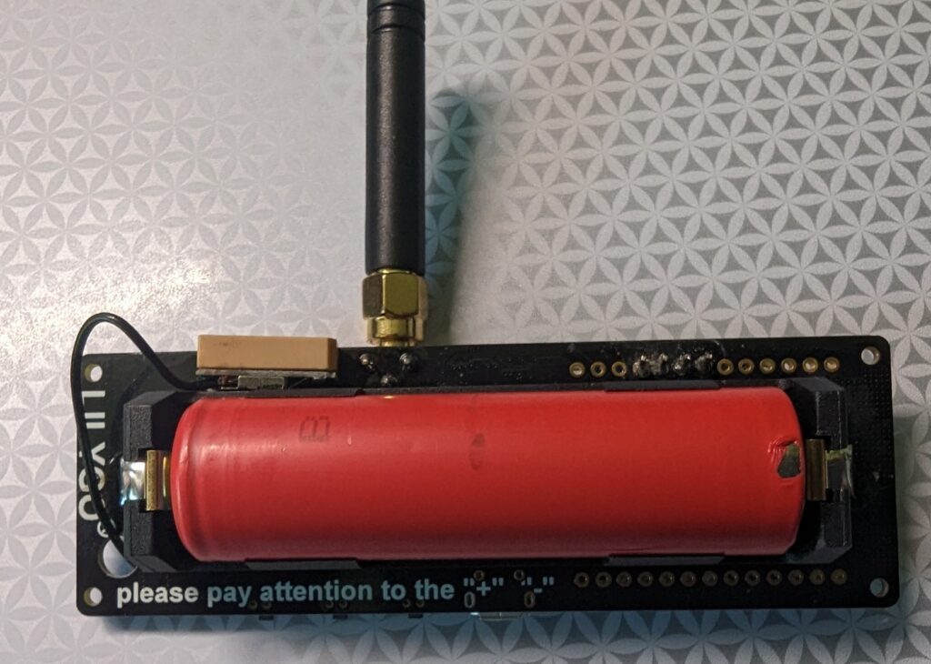
On the back of the board, there is a battery holder for an 18650 3.7 V lithium ion battery to power the board. The board can also be powered through the microUSB port, which also recharges the battery. There are other similar LoRa32 boards that you can use for these projects, and they are readily available on Amazon, eBay, and other online retailers.
Front and back of TTGO T-Beam v1.1 ESP32 433MHz LoRa32 board
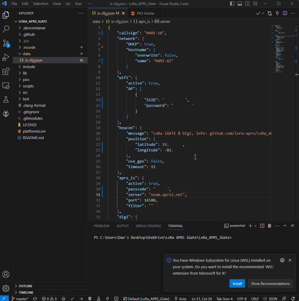
Programming the board is fairly easy. The iGate and tracker project pages on GitHub include links to quick start guides. The quick start guides are in German and French, but you can right-click in Chrome and choose “Translate to English”. Even better, there is an excellent video by Tech Minds on YouTube that will take you step-by-step through the process of configuring and programming the iGate and tracker modules using Visual Studio Code with the PlatformIO plugin. This process will load the firmware onto the module, as well as a json configuration file that includes your callsign, wifi info (for the iGate), etc. I highly recommend viewing the Tech Minds video before you start these projects!
Lora APRS iGate json configuration file in Visual Studio Code
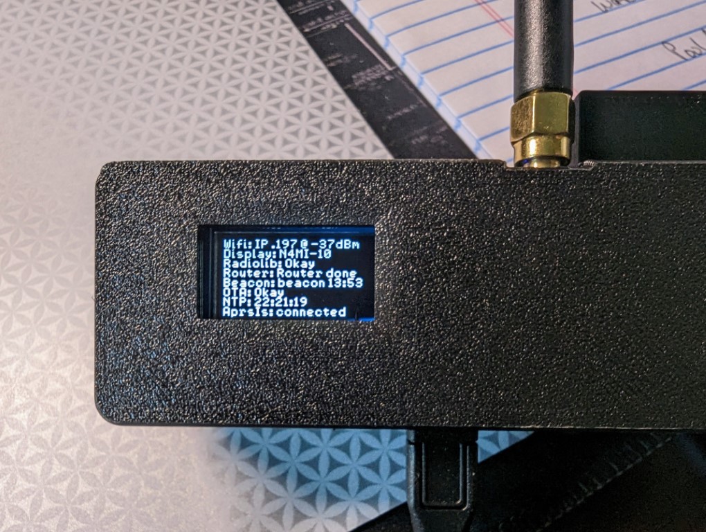
After programming the iGate and tracker, I was ready to test! I missed a step in my initial configuration of the iGate, so it did not connect to my home wifi on the first attempt. Once that was fixed, it connected to the internate and I was able to see the LoRa iGate symbol for my ssid N4MI-10 appear on the aprs.fi live APRS map. The iGate is operating on 433.775 MHz.
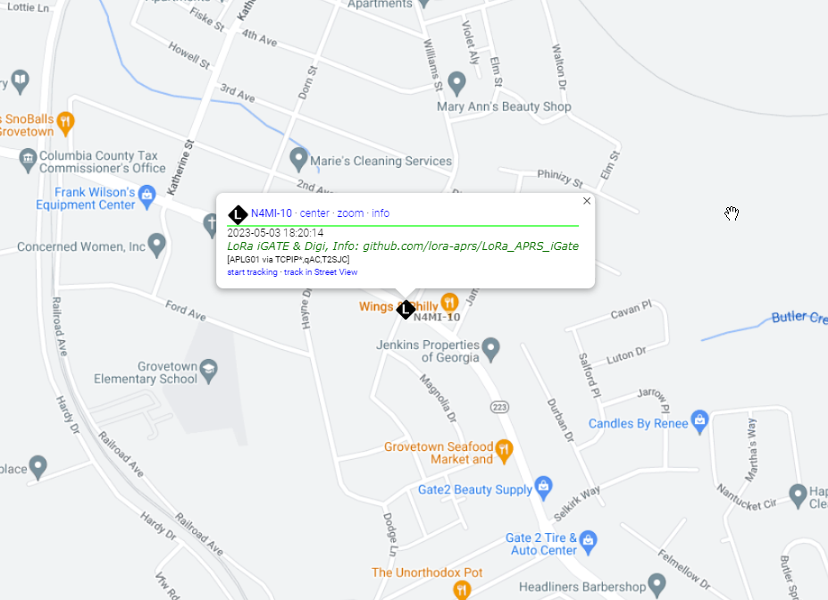
OLED screen showing LoRa APRS iGate configurationN4MI-10 LoRa APRS iGate, operating on 433.775 MHz, displayed on aprs.fi
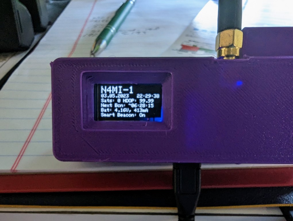
Once the iGate was operational, it was time to test the tracker. I chose N4MI-1 as the ssid for testing the tracker. I have some other APRS capable radios, so I will have to come up with a plan for assigning a ssid for each of them. The tracker powered up and initialized. Once it acquired enough satellites for a fix, I saw it transmit the first beacon, which was immediately picked up by the iGate. Awesome!
You can configure the tracker for smart beaconing in the json configuration file. You can also manually transmit a beacon using the middle button on the LoRa module.
OLED screen on LoRa 433 MHz APRS tracker
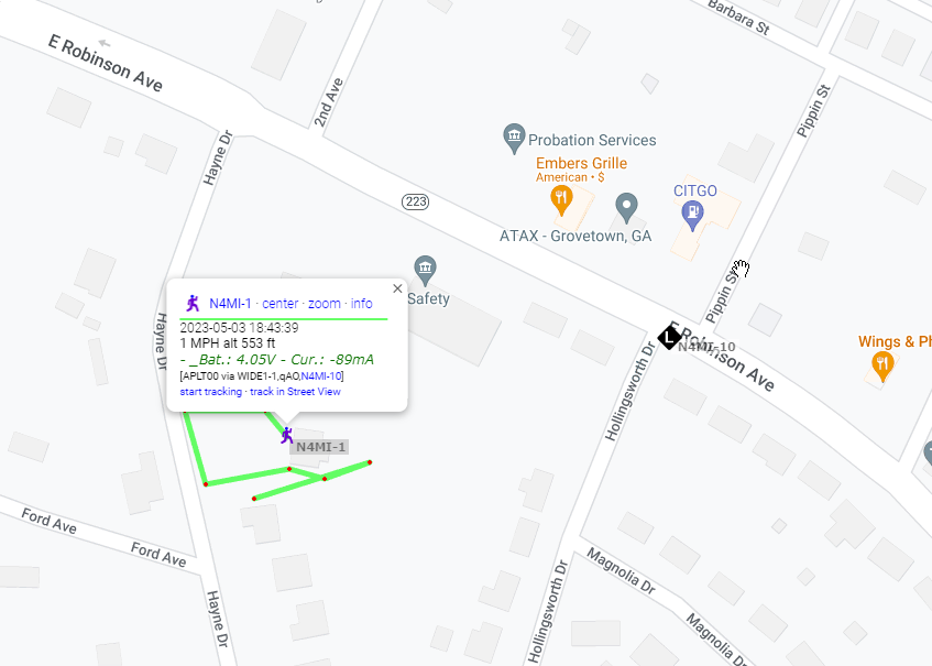
I took the tracker out for a short walk, and transmitted a beacon from several locations, all of which were received by the iGate and displayed on aprs.fi.
Positions from N4MI-1 LoRa 433 MHz APRS tracker displayed on aprs.fi
The transmitter in the LoRa board is very low power, about 200 mW, so the range with the small SMA antenna is limited. The range can be extended by using a better antenna at a higher elevation. Additionally, a small RF amplifier could be used to increase the power.
This was a very fun and relatively easy project. I am planning to attach a 70cm antenna at a higher elevation to the iGate in case other hams in this area would like to build and use LoRa 433 MHz APRS trackers.
The Icom IC-705 is an amazing QRP transceiver with lots of advanced features. Those features include built-in Bluetooth and wireless LAN, creating opportunity for display and control the IC-705 remotely. Some excellent free software recently became available to take advantage of the Bluetooth capability for a remote display using an inexpensive IoT development board. Also, an incredible iPad app was recently released that allows full remote display and control of the IC-705 via WiFi or LAN.
Remote S Meter and MultiMeter Projects with M5Stack
There are two very easy projects using code available on GitHub and an inexpensive M5Stack Core Development Kit: one to create a remote S Meter and another to create a more advanced and very useful remote MultiMeter.
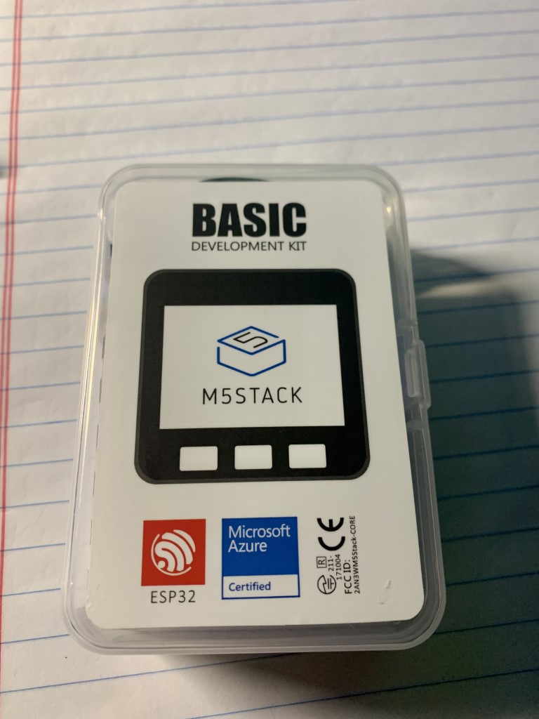
M5Stack Core Development Kit
The M5Stack is an ESP32 development system for IoT applications. This extremely powerful yet low-cost chip includes Wi-Fi and Bluetooth and has quickly become popular over the past year or so. The M5Stack Core Development Kit is currently available on Amazon for about $50.
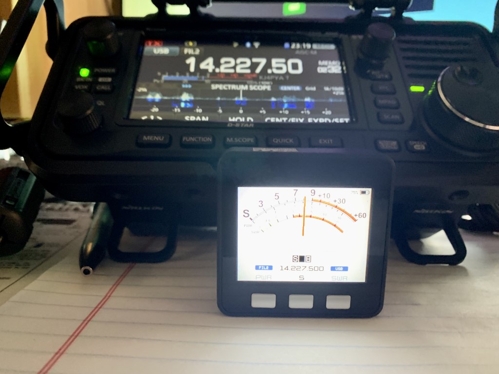
The first project I completed using the M5Stack was the IC705SMeter, created by Armel, F4HWN. Once the code is installed and the M5Stack is connected by Bluetooth to the IC-705, it has a selectable display of the received signal strength, output power, and SWR. It also displays the current frequency, mode and filter. It was very easy to install the software and connect to the IC-705 by following step by step instructions in a YouTube video by Ham Radio Dude.
Remote S-Meter connected to IC-705 via Bluetooth
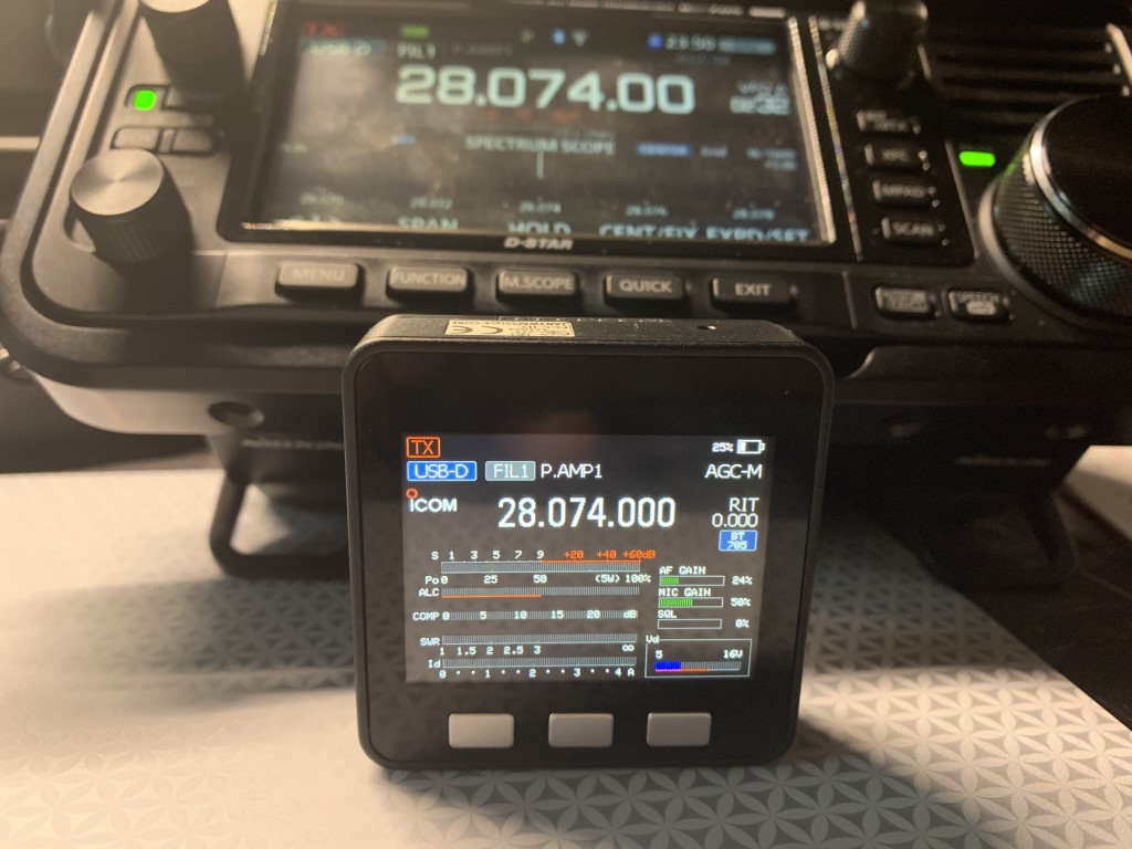
There is also another more advanced remote meter project, also created by Armel, called the ICMultiMeter. This project allows you to display the equivalent of the meter screen of the IC-705 on the M5Stack screen, which allows you to dedicate the IC-705’s screen to the waterfall while seeing all the signal measurements simultaneously on the M5Stack screen. The installation process is very similar to the S Meter project. A YouTube video by Tech Minds has easy-to-follow instructions to build and install the remote MultiMeter.
IC MultiMeter connected to the IC-705 via Bluetooth
SDR Control Software for iPad
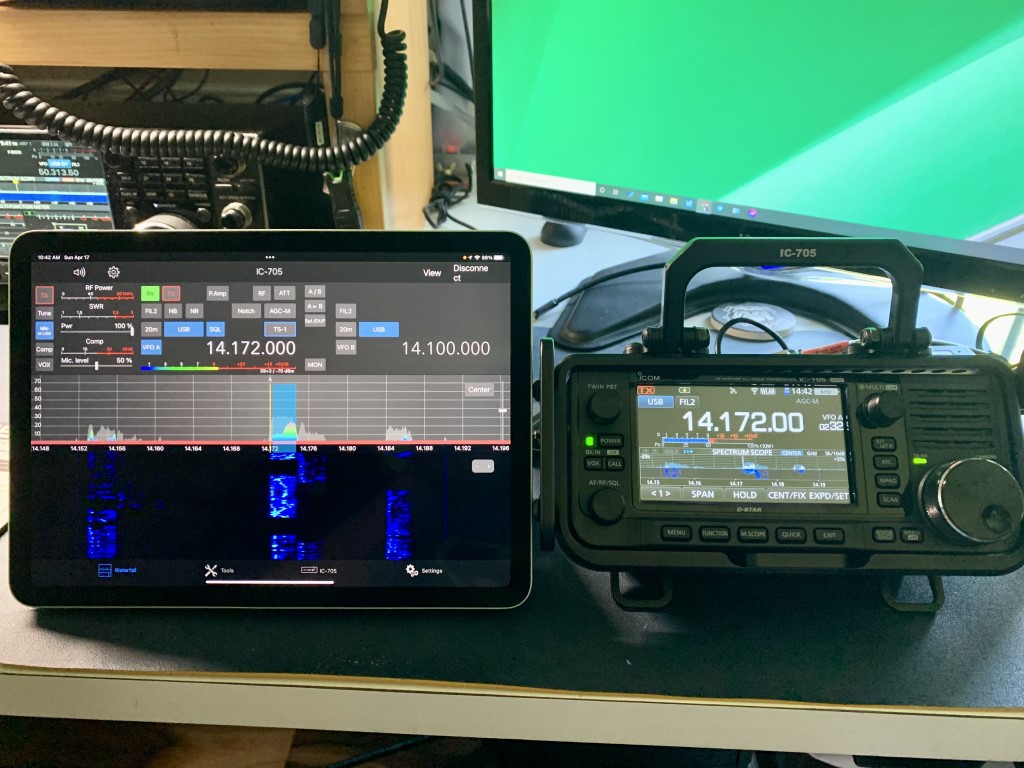
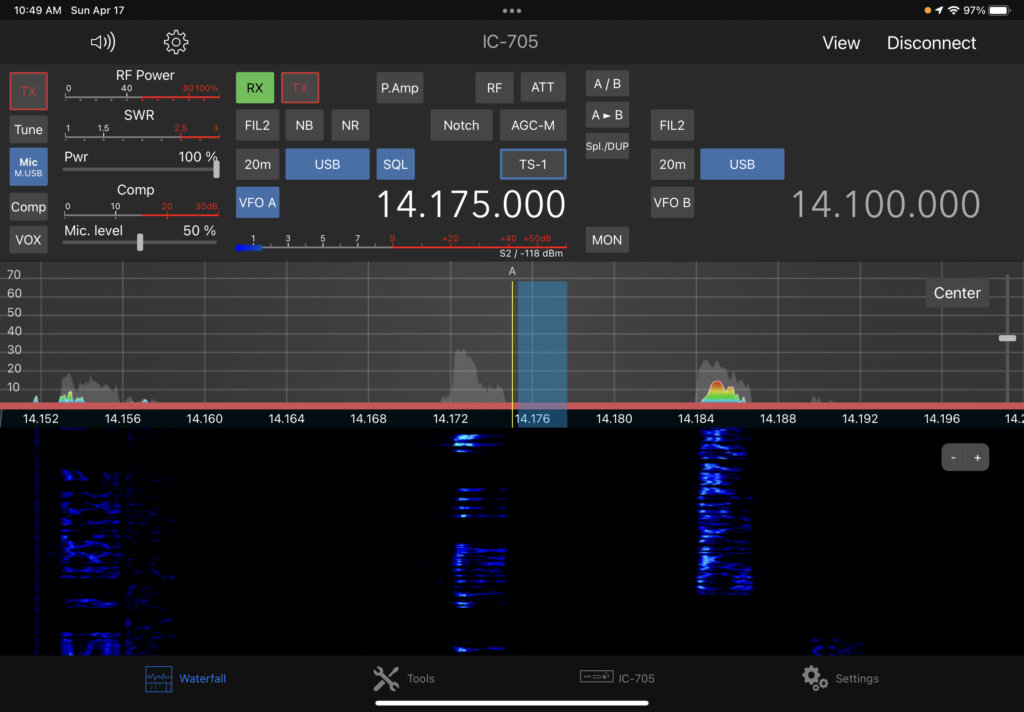
Having a remote meter is wonderful, but what if you’d like to have a full remote display and control of the IC-705? An application recently released for iPad will do just that. SDR-Control for Icom, available on the App Store, allows remote operation of the IC-705 without additional hardware or software. The app costs $50, but has tons of features, to include an integrated logbook, CW keyer and FT8/FT4 tool. An important caveat is that the IC-705 and iPad must be connected to the same WiFi network. The app will also control IC-7610 and IC-9700 transceivers connected to the same network via LAN. A YouTube video by Tech Minds provides an excellent overview of the SDR-Control app.
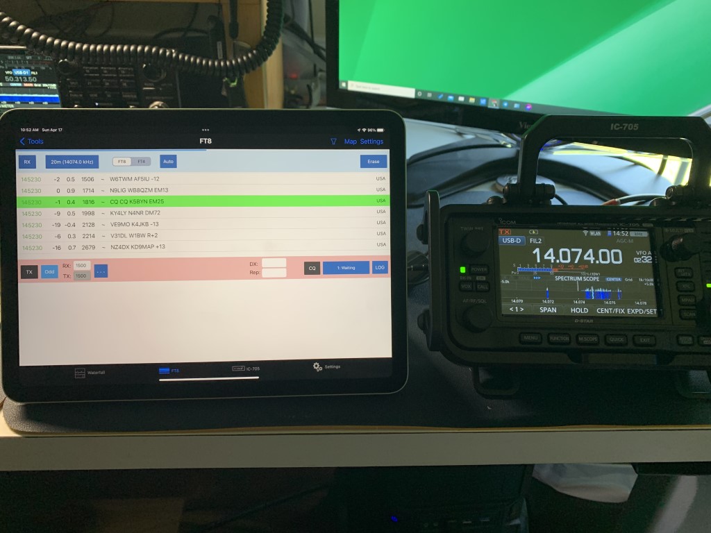
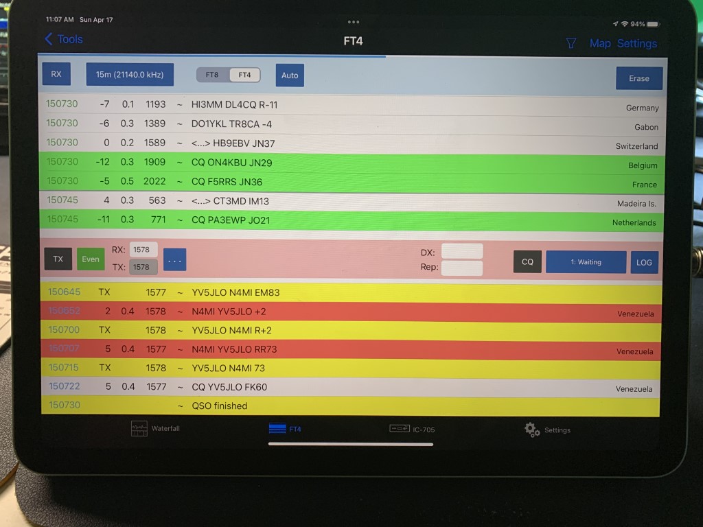
Once installed on the iPad, the app includes an integrated instruction manual explaining all of the functions, to include connecting the app to the IC-705. There is also an online version of the instruction manual. Following the instructions in the manual, I was able to connect to the IC-705 in just a few minutes. I found the app to be very easy to understand and use. When using the integrated FT8/FT4 tool, I did have to consult the manual to adjust the signal levels. Once that was done, it worked very well. The FT8/FT4 tool does not have all of the functionality of WSJT-X (no DXpedition mode), but it works well for casual operating. So far I have only used the app with the IC-705. I don’t yet have my IC-7610 or IC-9700 connected to my home network, but I plan to do that soon so that I can control the transceivers from anywhere in the house.
SDR-Control app connected to the IC-705 via WiFiScreen shot of the SDR-Control appIntegrated FT8/FT4 tool in SDR-ControlI made several FT8 contacts using the integrated FT8/FT4 functions in the appWaterfall screen on the SDR-Control app showing stations sending FT8 signals
I wanted to incorporate some of my most recent ham radio activities into a new QSL card. I reached out to my friend Jeff, K1NSS, and gave him a basic idea about what I wanted. I wanted my DX hound buddy Luke the Catahoula featured in the card. As usual, he worked his magic and came up with a fantastic design that captured my vision, and then some! What do you think? This version will be going to the printer soon.
WSPR (pronounced “whisper), which stands for “Weak Signal Propagation Reporter,” is a fantastic digital signal for assessing band conditions and evaluating antenna performance. It’s also great for detecting band openings. WSPR mode implements a protocol designed for probing potential propagation paths with low-power transmissions. The protocol was designed, and a program written initially, by Joe Taylor, K1JT. WSPR is included in the WSJT-X software, along with several other weak signal digital modes (FT8, FT4, etc.) for amateur radio. WSJT-X can be used to transmit and receive WSPR signals.
WSJT-X v.2.3.1 receiving and decoding WSPR on 20m.
There may be times when you don’t want to tie up your HF transceiver for WSPR signals, and you really don’t need the power that’s available in most HF transceivers for WSPR. With a decent antenna, you can transmit and decode signals over very long distances with very low power. Because of the encoding of the WSPR signal, a 200 mW signal has the same DX capability as a 1 KW SSB transmitter, or CW at 80W.
You can search the Internet for information on how to build your own transmitter, and there are also some kits for sale. There are also a couple of relatively inexpensive and small WSPR transmitters that are easy to configure and use. I have been using the WSPRlite Classic, made by SOTABEAMS, and two WSPR Desktop Transmitters, made by ZachTek. There are some common features between the two, but there are also quite a few differences. Both transmit a 200 mW signal using 5V (USB) input for power, and both use software for configuring your callsign, location, etc. They can also be powered from a USB power bank.
The WSPRlite and WSPR Desktop transmitter require 5V power and programming through a USB input (micro USB). Both have a SMA connector for the antenna, so a SMA male to PL-259 adapter may be useful for connecting to your antenna.
SOTABEAMS WSPRlite
The first WSPR transmitter I started using is the WSPRlite, which costs around $140. It is very small and light, and therefore great for portable operations. The unit contains internal filters for 20m and 30m, but SOTABEAMS also sells filter kits to expand the capability to include 630m, 160m, 80m, 60m, and 40m. I have not purchased or used any of the filter kits.
The WSPRlite is very small!
A unique feature from SOTABEAMS that comes with the WSPRlite is the DXplorer web site.
The WSPRlite instructions, configuration app, USB drivers, and firmware updates are available on DXplorer. Following the detailed instructions from the website, configuring the WSPRlite is a relatively easy process that involves installing USB drivers and configuration software, connecting to the computer through a USB port, selecting the appropriate COM port, entering data for a few settings, and saving the settings to the device. Once configured, the WSPRlite is ready to transmit. The trickiest part to begin transmitting is pressing a button 2 seconds after the start of an even numbered minute (i.e. 14:58:02, 10:20:02, etc.) to begin transmission. The time must be set accurately for the transmitted signals to be decoded.
Windows Device Manager will display the COM port. The WSPRlite is on COM14.The WSPRlite configuration software is very easy to understand. Enter the callsign, Maidenhed grid locator, band, desired power level (5 mW – 200 mW). There is also a link to the DXplorer site to view statistical analysis of the WSPR signals you transmit.
The configuration application also provides a link to dxplorer.net, where you can view statistics and maps depicting the WSPR signals transmitted from the WSPRlite. There are several different ways to view the data, including a metric call DX10. According to SOTABEAMS:
We use the WSPR data to generate a special metric, DX10. We recalculate your DX10 range (km) every two minutes. DX10 is a great system performance indicator. The best HF system will give the longest DX10 ranges. … Within seconds of your two-minute WSPR transmit period ending, you can see where you have been heard.
The main page for my callsign in DXplorer, with links to view maps, tables, and graphs. You can also change the band and callsign.You will probably want to view the Spots Map first, for a visual representation of where your WSPR signal is being received. It is a zoomable Great Circle map centered on your QTH. WSPR only uses the first part of your locator so your exact QTH could be some tens of kilometers from your actual location. The map shows the location of stations that have received your signal over the selected period. The colors relate to signal levels. You can “mouse-over” the spots to see additional data.The Spots Table provides more details about the stations that decoded your signal. It shows the raw WSPR data for your selected time period. This is useful as it allows you to see all the stations who spot you not just the DX10 list.The DX10 table gives you a snapshot of your system performance. However it does more as it identifies the time ranges for the spots so that you can identify the best times for DX openings. At the bottom of the table is a “DX10 mean” for your 10 spots. If there are less than 10 spots the missing ones are assumed to have a range of 0 km.For the DX10 graph, each data point is calculated from all your spots in the previous hour. The best 10 spots (in terms of range) are used to calculate a DX10 mean. The mean is displayed on a graph which is updated every 2 minutes. The DX10 graph gives a good indication of your system performance and band conditions. You can “mouse-over” the graph to see additional data.
The DXplorer website is where the WSPRlite really shines. It’s easy to use and provides lots of useful informaton.
WSPR Desktop Transmitter
The WSPR Desktop Transmitter from ZachTek also costs $140, and is slightly larger and heavier than the WSPRlite, but has several additional features. The unit includes a GPS receiver and antenna, which can automatically set the location (grid) and control the timing of the transmissions. Once initially configured, this makes operation nearly automatic. Additionally, the latest firmware and software supports Type 3 WSPR Messages. A Type 3 message can transmit a more exact location using six figure Maidenhead reports instead of the regular four figure report, which is especially useful if you use the transmitter in a mobile or portable application with it functioning as tracker.
I am using two transmitters, each designed for operation on different bands. The “Mid” model transmits on 40m, 30m, 20m and 17m. The “High” model transmits 15m, 12m, 10m and 6m.
Note: ZachTek now sells three updated models for this transmitter: – “Low” for 2190m and 630m – “Mid-Plus” for 160m, 80m, 40m, 30m, and 20m – “High-Plus” for 17m,15m, 12m, 10m and 6m You can purchase multiple units at a discount ($254 for a Mid-Plus and High Plus, or $359 for all three models).
WSPT Desktop Transmitter with the GPS antenna.
The WSPR Desktop Transmitter also uses an app for configuration. The documentation web page has links to the configuration software, a quick start guide, and lots of additional details about the transmitter. A USB driver might be required to connect to the computer, and there is a link on ZachTek’s download page. Similar to the WSPRlite, once the device connected to the computer with the micro USB cable, you can determine COM port using Windows Device Manager. You set the serial port (for my computer, COM13) on the Serial Port tab, and click open. After a moment the software will be connected to the device.
The Serial Port tab on the WSPR Transmitter Configuration application.
After the connection is open, the next tab to click is WSPR Beacon. This is where you will enter your callsign, and select the bands. With the GPS antenna connected and placed near a window, you should start seeing the GPS signal quality and a position lock. Once the position is locked, the Maidenhead grid information will fill in automatically. When initially powered up, it might take several minutes to start seeing the satellite positions and get a position lock.
Beacon configuration for the “Mid’ model, to transmit on 40m, 30m, 20m and 17m.Beacon configuration for the “High” model, to transmit on 15m, 12m, 10m, and 6m.
Once the WSPR configuration is complete, click on the Save Settings button, then click on the Boot Configuration tab. In this tab, you can configure the transmitter to start up in WSPR beacon mode. When power is applied, once it achieves a GPS position lock, the unit will automatically start transmitting WSPR beacons, cycling through the bands that were set in the WSPR Beacon tab.
The Boot Configuration tab is for setting up the transmitter to automatically obtain a GPS lock and begin transmitting WSPR when it is powered up.
There is also a Signal Generator mode so the transmitter can be used as a piece of test equipment in your shack. It can output a 23dBm sine wave from 2kHz to 50MHz, depending on model. I have not tested or used this feature.
The WSPR Desktop Transmitter includes a Signal Generator mode
The WSPR Desktop Transmitter does not include access the DXplorer website like the WSPRlite, but you could still use DXplorer standard mode to view statistics for signals transmitted from either device. You can also view maps and data for WSPR signal on the WSPRnet.org website. You can get a free account to access all of the features on WSPRnet.
The Weak Signal Propagation Reporter Network is a group of amateur radio operators using K1JT’s MEPT_JT digital mode to probe radio frequency propagation conditions using very low power (QRP/QRPp) transmissions. The software is open source, and the data collected are available to the public through this site.
http://wsprnet.org/drupal/
Front page of the WSPRnet web site
The Map tab opens a configurable map for a visual representation of where your WSPR signals are being decoded.
Map view on WSPRnet
Scroll down in the map to configure the view. There are several settings that you can use to tailor the information displayed on the map.
Map view configured to show spots for callsign N4MI on 30m over a period of 12 hours.
Click on the Database tab at the top of the web page to display a sorted list of spots. This view can also be configured.
Spots for callsign N4MI on 17mThe Database view can also be configured to filter the data and how the the details are presented.
Final Thoughts
The WSPRlite and WSPR Desktop Transmitter both performed very well. There are some difference in features and operation. For the price, the WSPR Desktop Transmitter offers a few more features and once configured it operates automatically every time it’s powered up. The WSPRlite is very small and easy to carry, and the DXplorer website offers excellent statistics for those tracking propagation conditions or comparing antennas. You can’t go wrong with either option, and your choice would depend upon your operating preferences.
This afternoon I finally got around to building a go-box for HF. I’ve had all of the components for a long time, but just never got around to the build. I would like to thank my friend Rusty, KG4HIR, who did most of the work on this build. This go-box is now ready to operate, but I hesitate to say it has been completed because there is still some empty space in the box to work with!
Here is a list of the primary materials used for this go-box:
Icom IC-7300 MFJ 4230MVP 30A Switching Power Supply with PowerPole Connectors MFJ 939I Autotuner Icom SP-35 External Speaker West Mountain Radio Epic PWRgate West Mountain Radio RIGrunner 4004 USB Mounting Brackets for IC-7300 and Power Supply Heavy Duty Hook and Loop Fastener Roll Gator Case Molded 4U Rack Case Two 1U Rack Mount Shelves 2U Rack Mount Panel Spacer with Venting NEMA 5-15R Plug Adapter with Mounting Holes 3 ft. USB Cable B to B – F/M – Panel Mount USB Extension M6 Terminal Binding Post 10 AWG Red/Black Zip Cord 45A Anderson PowerPole Connectors RG-8X Coax Jumper Cables UHF F-F Bulkhead Adapter Heavy Duty Velcro Strips
This is not intended to be a step-by-step tutorial for the build, but we did capture lots of images to give you an idea of how the go-box was assembled.
Rusty, KG4HIR, did the hard work on this project! Here we have the materials gathered. We had mounting brackets for the radio and power supply, but not for the MFJ autotuner. Rusty is preparing to secure it with heavy duty hook and loop fastener strips.The 4U rack mount case before installing the components.More components used for the go-box: 10 gauge zip cord, zip ties, HF4 to PowerPole adapter, RIGrunner, and Epic PWRgate.The Icom IC-7300Preparing the hook and loop fasteners to secure the MFJ autotuner. In the future, we may create some brackets to secure it better, but the hook and loop fasteners are secure and very strong.The MFJ autotuner and power supply attached to the top of the shelf. The mounting bracket for the IC-7300 is attached to the bottom side of the shelf.The IC-7300 mounting bracket was secured to the bottom of the shelf that also holds the autotuner and power supply.After looking at several configurations, we determined that mounting the PWRgate and RIGrunner upright would be more practical for adding and removing cables. They are secured to a piece of square aluminum tubing that is attached to the rack mount shelf at the back of the case.All of the primary components are secured to the shelves inside the case. For convenience, the primary connections into the go-box (AC power, ground terminal, USB cable to radio, and bulkhead connector for coax) are fitted to a vented panel spacer that is mounted at the top on the back of the case.Beginning the process of making DC power and RF connections inside the go-box.All of the connectors are attached to the vented panel spacer, and it is ready to be secured.Completing all connections for power, tuner, USB, and coax.The back of the (nearly) finished go-box. There is still some available space in the back and front of the case. Some of it will be left for airflow and ventilation, but we are considering whether some additional components could be added.The front of the (nearly) finished go-box. You can see the external speaker and the open space at the center top and right side bottom shelf. We may put a meter in the top space, and create a storage compartment at the bottom.
I was told that a go-box is never really finished, and that there will be changes and additions. The Epic PWRgate in this go-box makes it very versatile. It can be powered by AC via the power supply, as well as by a battery and/or a solar panel.
This build took a little over four hours. Much of that time was spent measuring, aligning, drilling and cutting to attach the components to the shelves and spacer. I still need to add some ferrite beads on several wires and cables. The next step after that is a field test to ensure everything is working properly. (That will be a topic for another post.) Once the testing is complete and it is confirmed to be fully operational, I will use the go-box at club operating events and for casual operating from the tailgate or patio.