Last month, I was given the opportunity to participate in a 30-day test and review of the Bilal Isotron 40M antenna for the 100 Watts and a Wire podcast. The Isotron is a strange looking and compact antenna that has reviews with an overall rating of 4 stars on eham.net. After building and then testing the antenna for a month, I was invited to participate in the podcast along with two other hams to give our review of the antenna for the following criteria:
You can listen to the podcast here. In addition to the audio podcast, there are videos covering each of the review criteria on the 100 Watts and a Wire YouTube channel. (Each of the criteria listed above includes a link to the YouTube video for that topic.)
Assembling the Antenna
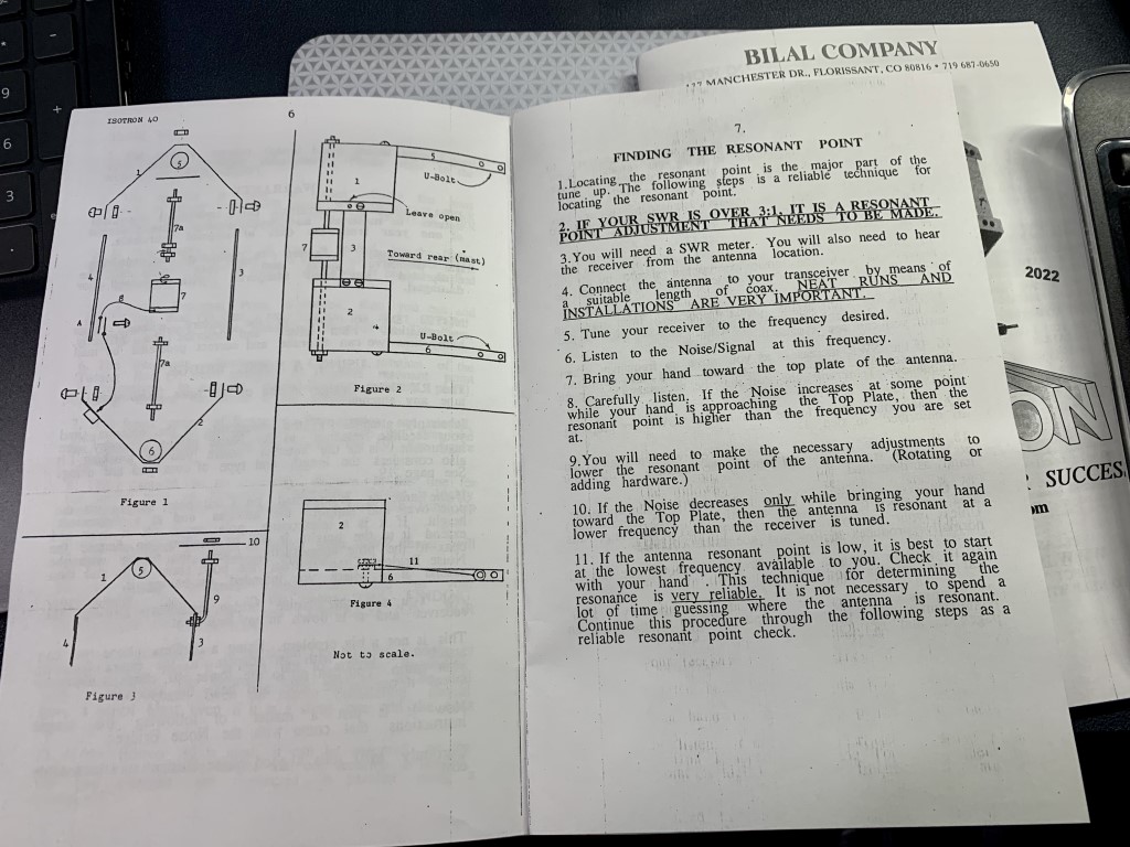
The antenna arrived in a sturdy box, and all of the parts were in good shape. The paper manual is adequate and includes diagrams that were helpful for assembly. It took me about an hour to put it together. Once assembled and tightened, it is a sturdy antenna. It’s worth reading the manual closely before attempting assembly, and again afterwards to understand the instructions for tuning the SWR.
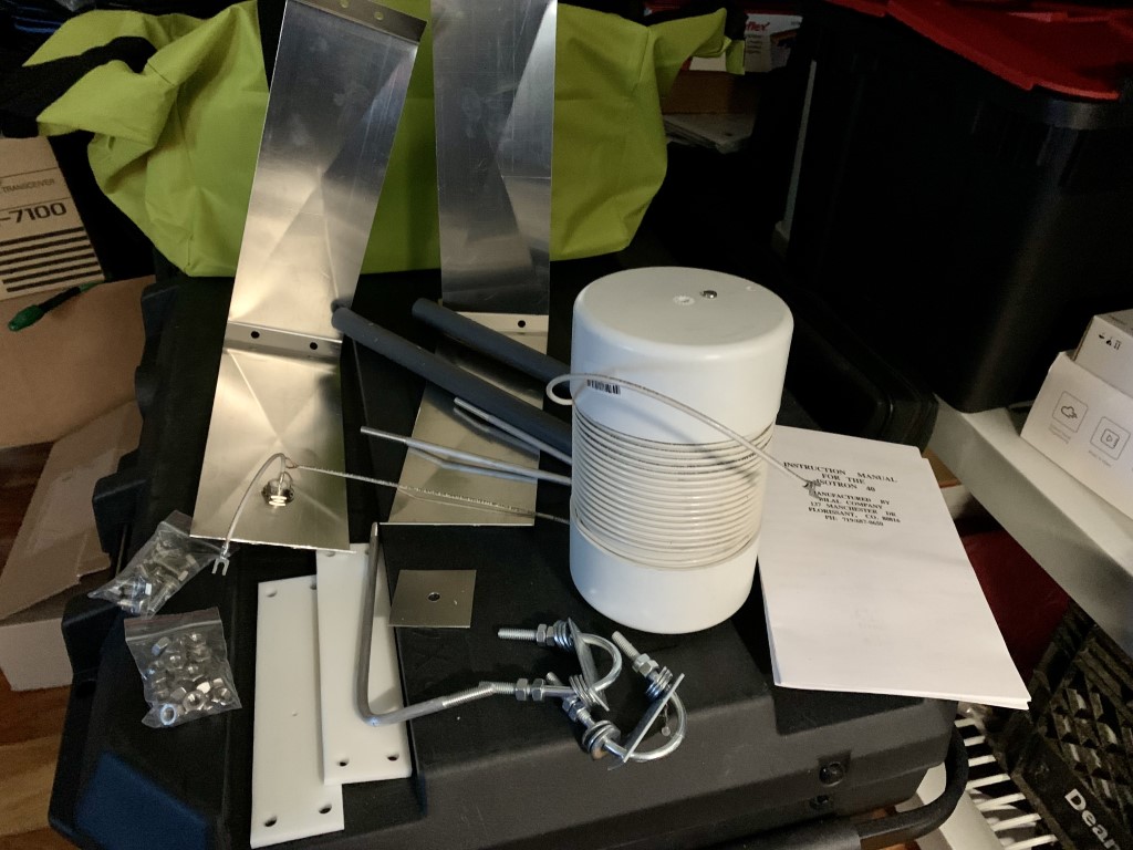
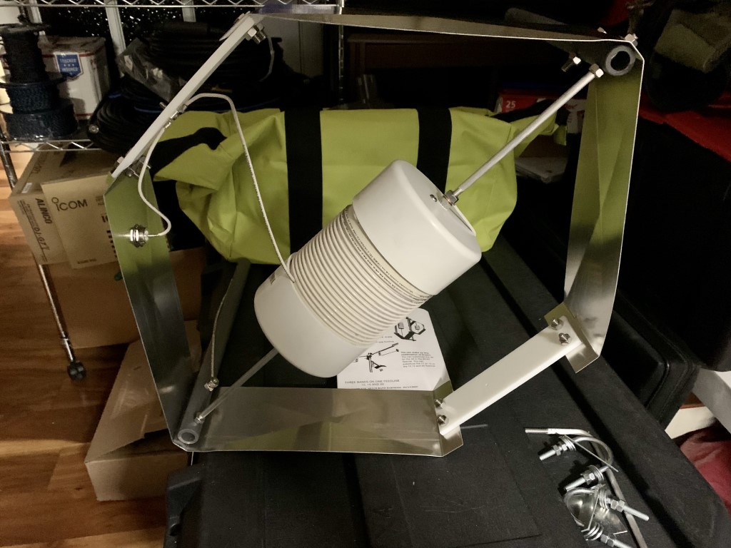
Photo of all parts prior to assembling the antennaThe manual is not fancy, but includes good instructions to assemble the antenna. Pay close attention to the instructions for tuning the antenna.The antenna is almost fully assembled, with the U-bolts for the mast and tuning arm still to be installed.
Installing and Testing the Antenna
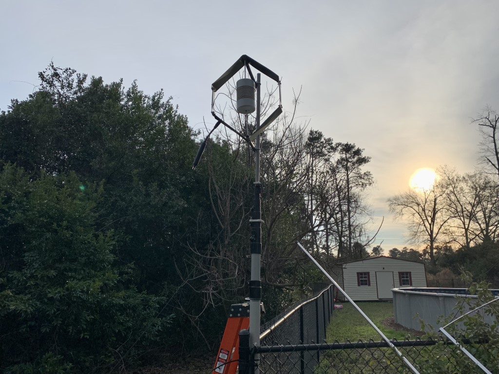
I installed the antenna on 28-foot heavy duty fiberglass telescoping mast from Max Gain Systems. The mast is located next to a long chain link fence, which may have interacted with the antenna and made tuning it a bit challenging initially. Once attached to the mast, I used a Comet antenna analyzer, and attempted to tune the antenna for the lower end of 40 meters for CW and digital modes. For my first test, with the antenna mast lowered, the SWR was just above 3:1. I believe that was partially due to close proximity of the metal fence. Also, the manual specifies that the antenna works best with a metal mast, likely to serve as a counterpoise. I attached about 25 feet of copper wire to the antenna ground as a counterpoise, and made some more tuning adjustments. After that, and when I raised the antenna to 25 feet, the SWR was down to 1.6:1. Close enough, since I have an antenna tuner in the shack.
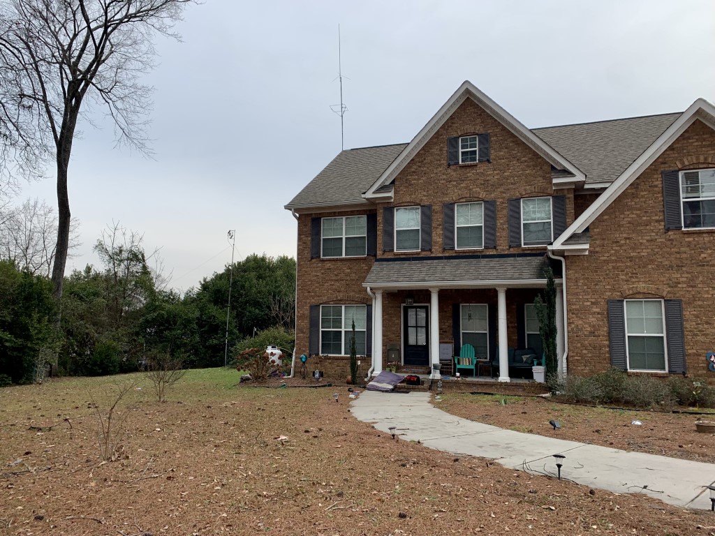
I mounted the antenna on a HD fiberglass telescoping mast. The mast was lowered to mount and tune the antenna. This picture shows a HF choke at the feed point, which I ended up removing after testing.The mast extended with the antenna about 25 feet off the ground.From a distance, the antenna is not quite as noticeable as the roof-mounted VHF/UHF vertical and 6M horizontal loop antennas.
Performance
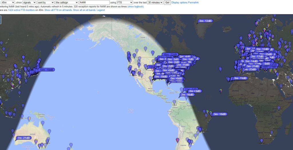
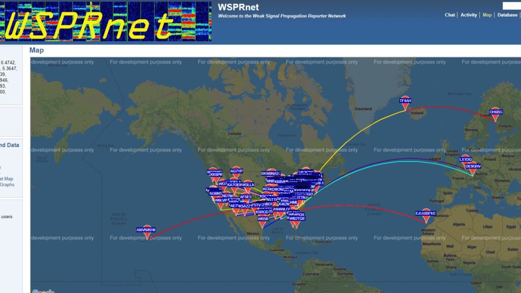
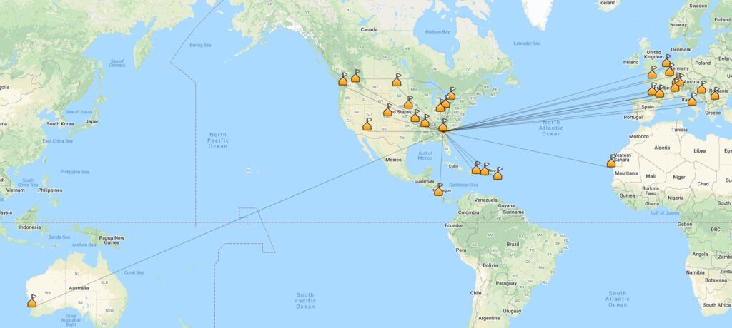
I tested the antenna for 30 days using FT8, WSPR, CW and SSB. The first contact I made on FT8 was in Washington State… a very promising start! Using FT8, I was easily able to work stations all over North America, as well as some DX stations in Europe, Australia and Japan. I also tested the antenna using WSPR for 24 hours, and my signals were received across North America and in Europe. I used the antenna for all of my 40 meter phone and CW contacts during Winter Field Day, and I was able to make a lot of contacts across the U.S. and Canada. The antenna performs better than I expected it would. However, it is not a good for receiving when compared against my end-fed halfwave antenna. I made comparisons several days, and the wire antenna was always noticeably better for receiving.
Stations receiving FT8 signals from Isotron 40M antenna on January 19th, 202224 hour WSPR test with Isotron 40M antennaCompleted QSOs made with the Isotron 40M antenna as of January 20th, 2022
Final Thoughts
Pros: 1. It actually works! When I first looked at the antenna, I was skeptical. After testing it for 30 days, I realize there are some use cases where this antenna is a good choice. 2. This antenna would probably good for someone with HOA restrictions, as it is small enough to be hidden. However, keep in mind that my testing was with the antenna mounted at 25 feet and in the clear. 3. Because the antenna is compact and can be raised quickly, it would also be a good choice for portable operations or emergency communications. Cons: 1. The antenna is only for the 40 meter band. If you have space for several antennas, that’s probably not an issue. 2. The antenna can be somewhat finicky with SWR. It made several trips up and down a ladder, and lowered the mast a few times, to get it adjusted. I also had to retune the antenna after one particularly cold, windy, rainy day.
The antenna retails for $160. Would I have bought this antenna on my own? Probably not. During the podcast, each reviewer was asked to give a “signal report” between 55 and 59 as an overall rating of the antenna. My report was solidly in the middle with a 57. It is definitely strange looking, but the appearance and compact size belie an antenna that actually performs fairly well, as long as you don’t expect miracles. I will most likely take the antenna down from the mast to install an off-center-fed dipole, and see if one of my ham friends living in a HOA community would like to give the Isotron a try.
This was a great ham radio experience for me. I had a lot of fun building, testing and using the antenna. I also enjoyed being included on the 100 Watts and a Wire podcast, and Christian Cudnick, K0STH, is a great host.
This afternoon I installed a new antenna for 10 meters. The antenna is a HF-28 Rectangle from PAR Electronics. It’s light (2.5 lbs.) and compact (approximately 8′ X 4′). It was very easy to build and took me about a half hour following the included instructions. I have the antenna mounted on a Max-Gain Systems MK-6 fiberglass push-up mast. The SWR was near perfect right away, but there are instructions included to tune the antenna if necessary. According to the manufacturer, the antenna is not perfectly omni-directional, but it has a pattern that does not require a rotator.
The antenna seems to work very well. The conditions on 10 meters were not great today, but right away I was able to work several FT8 stations on the west coast and in South America. I can’t wait to see how it performs in good band conditions. Hopefully this antenna will help me finally work Alaska on 10 meters to finally complete a 5BWAS and get closer 10 DXCC for 10 meters!
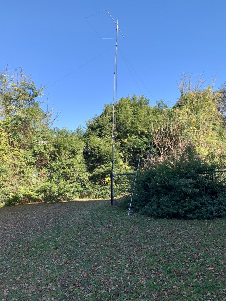
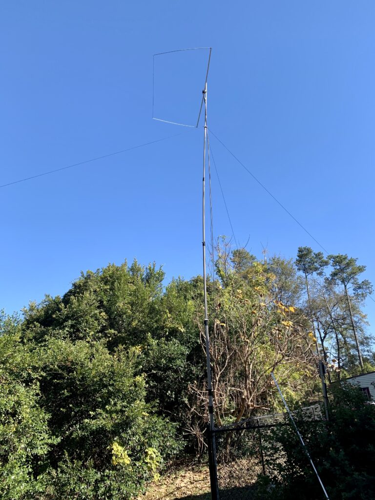
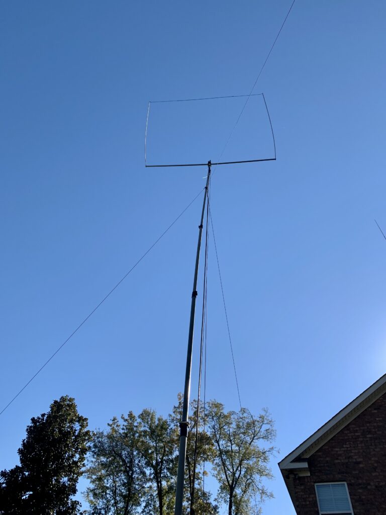
The antenna is mounted on the mast I had previously used for a 6 meter Ringo vertical, which you can see leaning up against the fence.I still need to do some work on the guy ropes, but the antenna and mast are very sturdy.I only need 9 more countries for DXCC on 10 meters!
This weekend the higher frequency bands have really come to life. I have had a blast working stations in Europe, the Middle East, and Africa. I hope this is just a glimpse of things to come!
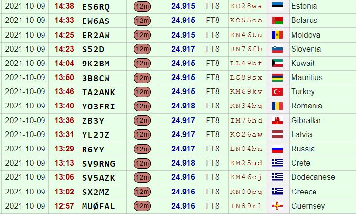
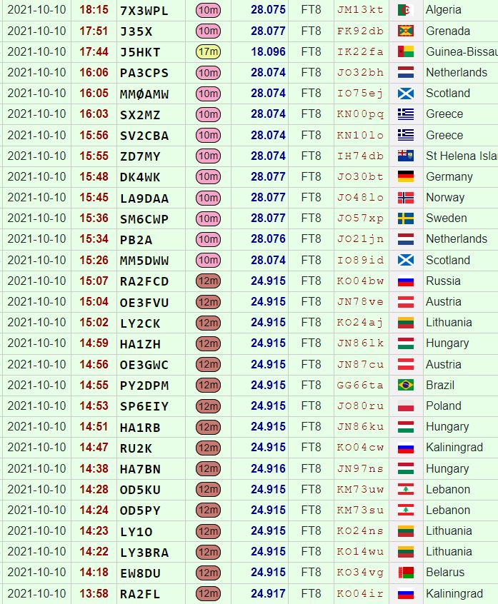
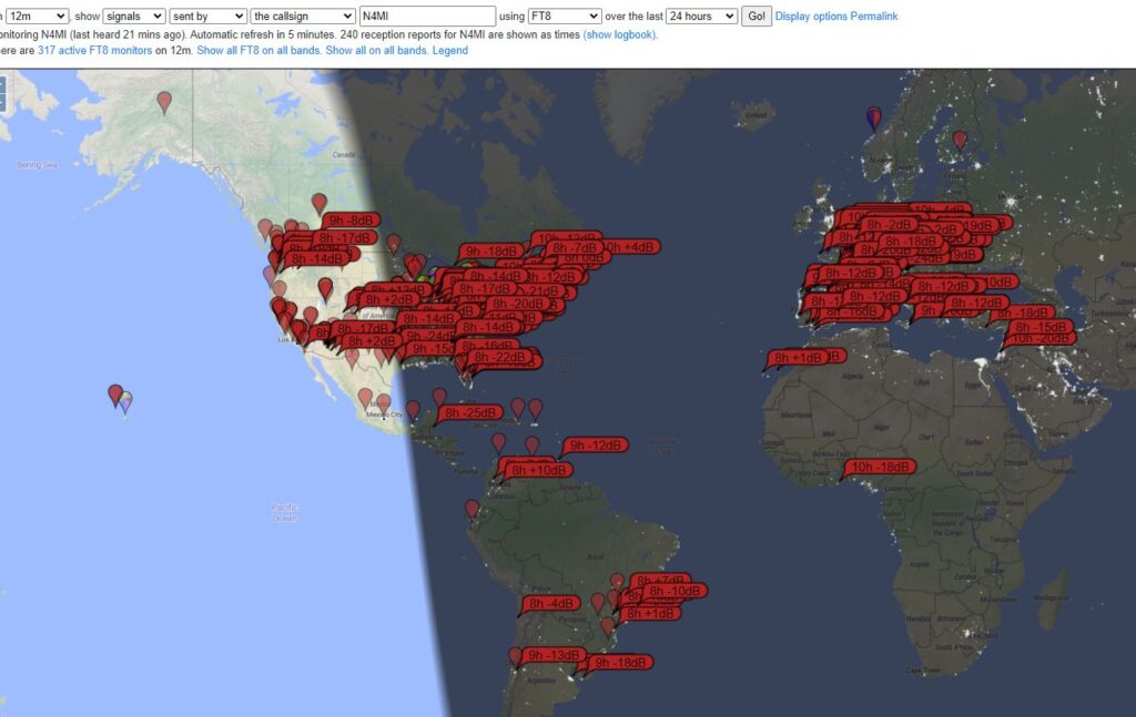
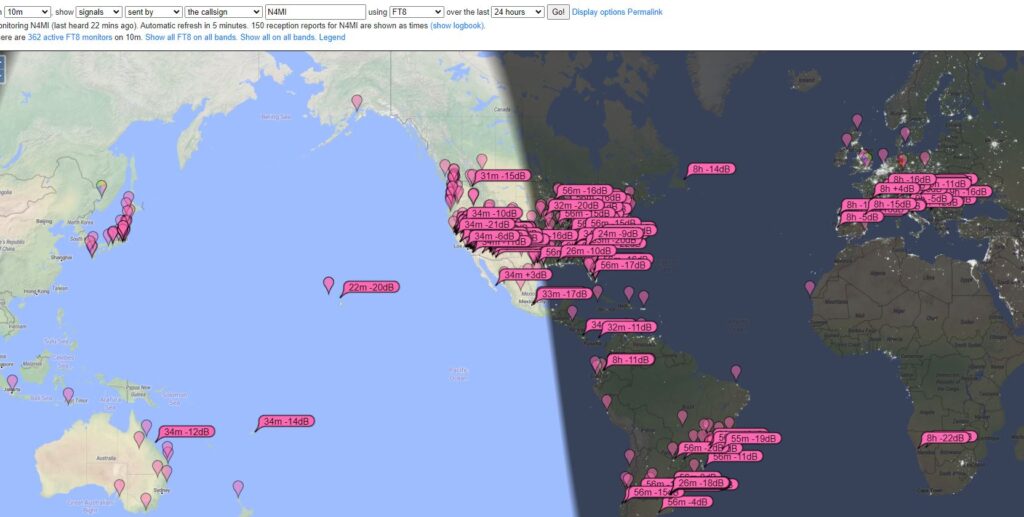
My 12m contacts on October 9th12m and 10m contacts on October 10th12m and 10m contacts on October 11thMap of stations that were receiving N4MI FT8 signals on 12m on October 11th Map of stations that were receiving N4MI FT8 signals on 10m on October 11th Logbook of the World confirmations as of October 11th
In three days, I logged 40 QSOs on 12m, in 29 different countries. I also logged 19 QSOs on 10m, in 17 different countries. I could have worked many more stations, but I was hunting specifically for new countries. I managed to work enough new countries for a DXCC Award for 12m. I still have some work to do on 10m, but I picked up a few more.
I am sure that many hams in the U.S. with better stations worked more countries, but I am happy with these results using less than 100 watts into an end-fed wire antenna.
WSPR (pronounced “whisper), which stands for “Weak Signal Propagation Reporter,” is a fantastic digital signal for assessing band conditions and evaluating antenna performance. It’s also great for detecting band openings. WSPR mode implements a protocol designed for probing potential propagation paths with low-power transmissions. The protocol was designed, and a program written initially, by Joe Taylor, K1JT. WSPR is included in the WSJT-X software, along with several other weak signal digital modes (FT8, FT4, etc.) for amateur radio. WSJT-X can be used to transmit and receive WSPR signals.
WSJT-X v.2.3.1 receiving and decoding WSPR on 20m.
There may be times when you don’t want to tie up your HF transceiver for WSPR signals, and you really don’t need the power that’s available in most HF transceivers for WSPR. With a decent antenna, you can transmit and decode signals over very long distances with very low power. Because of the encoding of the WSPR signal, a 200 mW signal has the same DX capability as a 1 KW SSB transmitter, or CW at 80W.
You can search the Internet for information on how to build your own transmitter, and there are also some kits for sale. There are also a couple of relatively inexpensive and small WSPR transmitters that are easy to configure and use. I have been using the WSPRlite Classic, made by SOTABEAMS, and two WSPR Desktop Transmitters, made by ZachTek. There are some common features between the two, but there are also quite a few differences. Both transmit a 200 mW signal using 5V (USB) input for power, and both use software for configuring your callsign, location, etc. They can also be powered from a USB power bank.
The WSPRlite and WSPR Desktop transmitter require 5V power and programming through a USB input (micro USB). Both have a SMA connector for the antenna, so a SMA male to PL-259 adapter may be useful for connecting to your antenna.
SOTABEAMS WSPRlite
The first WSPR transmitter I started using is the WSPRlite, which costs around $140. It is very small and light, and therefore great for portable operations. The unit contains internal filters for 20m and 30m, but SOTABEAMS also sells filter kits to expand the capability to include 630m, 160m, 80m, 60m, and 40m. I have not purchased or used any of the filter kits.
The WSPRlite is very small!
A unique feature from SOTABEAMS that comes with the WSPRlite is the DXplorer web site.
The WSPRlite instructions, configuration app, USB drivers, and firmware updates are available on DXplorer. Following the detailed instructions from the website, configuring the WSPRlite is a relatively easy process that involves installing USB drivers and configuration software, connecting to the computer through a USB port, selecting the appropriate COM port, entering data for a few settings, and saving the settings to the device. Once configured, the WSPRlite is ready to transmit. The trickiest part to begin transmitting is pressing a button 2 seconds after the start of an even numbered minute (i.e. 14:58:02, 10:20:02, etc.) to begin transmission. The time must be set accurately for the transmitted signals to be decoded.
Windows Device Manager will display the COM port. The WSPRlite is on COM14.The WSPRlite configuration software is very easy to understand. Enter the callsign, Maidenhed grid locator, band, desired power level (5 mW – 200 mW). There is also a link to the DXplorer site to view statistical analysis of the WSPR signals you transmit.
The configuration application also provides a link to dxplorer.net, where you can view statistics and maps depicting the WSPR signals transmitted from the WSPRlite. There are several different ways to view the data, including a metric call DX10. According to SOTABEAMS:
We use the WSPR data to generate a special metric, DX10. We recalculate your DX10 range (km) every two minutes. DX10 is a great system performance indicator. The best HF system will give the longest DX10 ranges. … Within seconds of your two-minute WSPR transmit period ending, you can see where you have been heard.
The main page for my callsign in DXplorer, with links to view maps, tables, and graphs. You can also change the band and callsign.You will probably want to view the Spots Map first, for a visual representation of where your WSPR signal is being received. It is a zoomable Great Circle map centered on your QTH. WSPR only uses the first part of your locator so your exact QTH could be some tens of kilometers from your actual location. The map shows the location of stations that have received your signal over the selected period. The colors relate to signal levels. You can “mouse-over” the spots to see additional data.The Spots Table provides more details about the stations that decoded your signal. It shows the raw WSPR data for your selected time period. This is useful as it allows you to see all the stations who spot you not just the DX10 list.The DX10 table gives you a snapshot of your system performance. However it does more as it identifies the time ranges for the spots so that you can identify the best times for DX openings. At the bottom of the table is a “DX10 mean” for your 10 spots. If there are less than 10 spots the missing ones are assumed to have a range of 0 km.For the DX10 graph, each data point is calculated from all your spots in the previous hour. The best 10 spots (in terms of range) are used to calculate a DX10 mean. The mean is displayed on a graph which is updated every 2 minutes. The DX10 graph gives a good indication of your system performance and band conditions. You can “mouse-over” the graph to see additional data.
The DXplorer website is where the WSPRlite really shines. It’s easy to use and provides lots of useful informaton.
WSPR Desktop Transmitter
The WSPR Desktop Transmitter from ZachTek also costs $140, and is slightly larger and heavier than the WSPRlite, but has several additional features. The unit includes a GPS receiver and antenna, which can automatically set the location (grid) and control the timing of the transmissions. Once initially configured, this makes operation nearly automatic. Additionally, the latest firmware and software supports Type 3 WSPR Messages. A Type 3 message can transmit a more exact location using six figure Maidenhead reports instead of the regular four figure report, which is especially useful if you use the transmitter in a mobile or portable application with it functioning as tracker.
I am using two transmitters, each designed for operation on different bands. The “Mid” model transmits on 40m, 30m, 20m and 17m. The “High” model transmits 15m, 12m, 10m and 6m.
Note: ZachTek now sells three updated models for this transmitter: – “Low” for 2190m and 630m – “Mid-Plus” for 160m, 80m, 40m, 30m, and 20m – “High-Plus” for 17m,15m, 12m, 10m and 6m You can purchase multiple units at a discount ($254 for a Mid-Plus and High Plus, or $359 for all three models).
WSPT Desktop Transmitter with the GPS antenna.
The WSPR Desktop Transmitter also uses an app for configuration. The documentation web page has links to the configuration software, a quick start guide, and lots of additional details about the transmitter. A USB driver might be required to connect to the computer, and there is a link on ZachTek’s download page. Similar to the WSPRlite, once the device connected to the computer with the micro USB cable, you can determine COM port using Windows Device Manager. You set the serial port (for my computer, COM13) on the Serial Port tab, and click open. After a moment the software will be connected to the device.
The Serial Port tab on the WSPR Transmitter Configuration application.
After the connection is open, the next tab to click is WSPR Beacon. This is where you will enter your callsign, and select the bands. With the GPS antenna connected and placed near a window, you should start seeing the GPS signal quality and a position lock. Once the position is locked, the Maidenhead grid information will fill in automatically. When initially powered up, it might take several minutes to start seeing the satellite positions and get a position lock.
Beacon configuration for the “Mid’ model, to transmit on 40m, 30m, 20m and 17m.Beacon configuration for the “High” model, to transmit on 15m, 12m, 10m, and 6m.
Once the WSPR configuration is complete, click on the Save Settings button, then click on the Boot Configuration tab. In this tab, you can configure the transmitter to start up in WSPR beacon mode. When power is applied, once it achieves a GPS position lock, the unit will automatically start transmitting WSPR beacons, cycling through the bands that were set in the WSPR Beacon tab.
The Boot Configuration tab is for setting up the transmitter to automatically obtain a GPS lock and begin transmitting WSPR when it is powered up.
There is also a Signal Generator mode so the transmitter can be used as a piece of test equipment in your shack. It can output a 23dBm sine wave from 2kHz to 50MHz, depending on model. I have not tested or used this feature.
The WSPR Desktop Transmitter includes a Signal Generator mode
The WSPR Desktop Transmitter does not include access the DXplorer website like the WSPRlite, but you could still use DXplorer standard mode to view statistics for signals transmitted from either device. You can also view maps and data for WSPR signal on the WSPRnet.org website. You can get a free account to access all of the features on WSPRnet.
The Weak Signal Propagation Reporter Network is a group of amateur radio operators using K1JT’s MEPT_JT digital mode to probe radio frequency propagation conditions using very low power (QRP/QRPp) transmissions. The software is open source, and the data collected are available to the public through this site.
http://wsprnet.org/drupal/
Front page of the WSPRnet web site
The Map tab opens a configurable map for a visual representation of where your WSPR signals are being decoded.
Map view on WSPRnet
Scroll down in the map to configure the view. There are several settings that you can use to tailor the information displayed on the map.
Map view configured to show spots for callsign N4MI on 30m over a period of 12 hours.
Click on the Database tab at the top of the web page to display a sorted list of spots. This view can also be configured.
Spots for callsign N4MI on 17mThe Database view can also be configured to filter the data and how the the details are presented.
Final Thoughts
The WSPRlite and WSPR Desktop Transmitter both performed very well. There are some difference in features and operation. For the price, the WSPR Desktop Transmitter offers a few more features and once configured it operates automatically every time it’s powered up. The WSPRlite is very small and easy to carry, and the DXplorer website offers excellent statistics for those tracking propagation conditions or comparing antennas. You can’t go wrong with either option, and your choice would depend upon your operating preferences.
The first balloon, which carried a payload with a SPOT Trace GPS tracker and a GoPro camera, was designed climb to an altitude of 70,000 – 100, 000 feet before bursting and falling back to earth. A parachute was attached to the payload so it could return to ground intact for retrieval by a chase crew. We expected the payload to land approximately 50 miles east of the launch site, but the balloon traveled much farther than anticipated. The chase teams scrambled and the payload was successfully retrieved approximately 150 miles from the launch site. The camera captured some amazing images while the balloon was in the stratosphere. Some of the best pictures are featured in the linked news stories.
Photo captured from the high altitude weather balloon shortly after launch. This camera captured lots of amazing images during this balloon flight.One of the many spectacular views captures by the camera on the high-altitude weather balloon.
This post focuses primarily on the second “pico” balloon, which carried only a LightAPRS-WAPRS and WSPR tracker as the payload, and was designed to reach an altitude of approximately 50,000 – 60,000 feet and achieve neutral buoyancy to travel for a much longer period of time. The LightAPRS-W, which is very small, was powered by two small PowerFilm 4.8V solar panels with two 5F 3V supercapacitors. With this power source, the tracker transmits APRS on VHF at .5 to 1 Watt, and WSPR on HF at 10 mW (1/100th of a Watt!).
We spent several days configuring and testing the tracker, using the configuration and programming instructions provided by QRP Labs on GitHub, and following some helpful suggestions in the Tips & Tricks for Pico Balloons wiki. The tracker also had two light wire antennas for APRS (19.4 inches) and 20 meter WSPR (16.6 feet), and a counterpoise (16.6 feet) attached.
Assembled LightAPRS-W tracker with two PowerFilm solar panels and super capacitors. It’s really small and light!
Once assembled, the tracker was easy to configure with an Arduino IDE to load the APRS callsign (K4KNS-11), WSPR callsign (K4KNS), and a few other settings. It’s best to pay very close attention to the instructions and comments in the configuration file! After the loading the configuration, we placed the tracker in the sun to test and listen for APRS and WSPR signals. We were able to confirm that the tracker was transmitting good APRS and WSPR signals. Due to the very low power of the VHF and HF transmitters, we could only confirm local reception. With the tracker stationary and in full sunlight, we noted that the LightAPRS-W transmitted an APRS packet approximately every 5 minutes, and a WSPR signal every 4-6 minutes.
Assembled and configured LightAPRS-W in the sun to test the solar panels and monitor APRS and WSPR signals.APRS received from the LightAPRS-W during testing.Good test of WSPR signal from K4KNS!
It’s one thing to have a good test under controlled conditions, but quite another to achieve success under field conditions. On the day of the launch, the weather was marginal, but within acceptable parameters for a launch. We double checked to ensure the tracker was powered up and transmitting, and tied it to the balloon.
Good test of the APRS signal on launch day!
We had a good launch. The balloon, with the tracker hanging 16.6 feet below the balloon (to accommodate the counterpoise) and trailing a 16.6 foot HF antenna, quickly rose to an altitude above any potential obstructions and began its journey. Within moments, we saw the first APRS positions appear on aprs.fi. A few moments later, using the WSPR Watch iPad app, we saw that the WSPR signal was being received across the U.S.!
The first APRS track for balloon K4KNS-11!The 10 mW WSPR signal was received as far west as Oregon!
It was all going so well! We continued to watch the balloon tracking eastward and climbing, following the same track as the high-altitude balloon that had been launched about a half hour earlier. Then, after about an hour of flight, both the APRS and WSPR signal went off the air. At that time the balloon was 55 miles east of the launch site at an altitude of 37,500 feet.
The track and final position received from K4KNS-11.Location, speed, course, speed, altitude, temperature, pressure and solar cell voltage data from K4KNS-11 exported from aprs.fi.
We’re not sure exactly why the signals were lost, but we do not believe the balloon went down in that location. We are speculating that the tracker may have been damaged due to the high wind speeds on lost power. It is unknown how much farther the balloon might have traveled. Despite the relatively short flight, we did collect some good data for the students at Savannah River Academy to evaluate. We also proved to ourselves that we could successfully launch a balloon and track it with APRS, and that a very weak WSPR signal transmitted from high altitude could be received by stations thousands of miles away!
Map on WSPRnet.org showing stations that received the K4KNS WSPR signal on May 5, 2021.Spot Database for K4KNS on on May 5, 2021 from WSPRnet.org.
Using aprs.fi’s data export tool, we were able to export a KMZ file with the balloon’s tracking data, and use Google Earth to view the full track and altitude changes.
Google Earth map of the track and altitude changes for pico balloon K4KNS-11 on May 5, 2021.
This was an amazing experience! We captured many lessons learned, and we intend to build another more hardened version of the tracker so we can launch another balloon and hopefully track it over a much longer distance and time.
I have been casually using DMR, D-STAR and YSF (Yaesu System Fusion) modes for a couple of years, using a ZUMSpot. The ZUMSpot is a small board that sits on a Raspberry Pi Zero W. It incorporates a Multimode Digital Voice Modem (MMDVM) and a 10mW UHF transceiver that operates YSF, DMR, YSF2DMR, D-Star, P25 and NXDN modes. The ZUMSpot uses Pi-Star digital voice software. Pi-Star is a custom, pre-configured SD Card image for the Raspbperry Pi, with configuration and operation performed through a web browser. The Amateur Radio Notes website has an excellent tutorial on setting up and configuring Pi-Star. While the Pi-Star configuration appears daunting at first, it is easy to set up by following the tutorial. There are also several videos on YouTube with instructions for configuring Pi-Star.
A few days ago, I was attempting to update the Pi-Star software and the ZumSpot firmware, but kept seeing errors during the firmware update. After several attempts to update the firmware, the ZumSpot wasn’t operating properly*, so I decided to purchase an openSPOT 3, which is made by SharkRF in Estonia.
The openSPOT3 is a battery powered, portable, standalone digital radio internet gateway (aka hotspot). The openSPOT 3 is also configured through a web interface, but the interface and steps for configuration are different than Pi-Star’s. The openSPOT 3 user manual is a web page that is updated frequently when there are firmware updates or features added to the device. Having learned the basics of DMR, D-STAR, and YSF with the ZUMSpot, I found configuration of the OPENSpot 3 to be fairly easy.
* After I had the openSPOT 3 up and running for a few days, I decided to attempt the ZUMSpot firmware upgrade again. It turns out I had missed a step in my earlier attempts, and this time the update was successful. So now I have two MMDVMs!
Both the ZUMSpot and OpenSPOT 3 are excellent MMDVMs. Both are capable of operating the most popular digital voice modes using a DMR, D-STAR or C4FM radio. Also, they both require a wi-fi connection and are configured through a web interface. The openSPOT 3 is great for portable operations since it has a built-in battery and the configuration web page works very well on a mobile phone web browser. Since the ZUMSpot is based on a Raspberry Pi Zero W, it could also be used portable with a USB power bank. The openSPOT 3 costs a bit more more than the ZUMSpot. There are also many other MMDVMs on the market, including inexpensive generic boards and kits available on Amazon and eBay. Digital voice modes with MMDVMs are a great way to talk to hams from all over the world using a VHF/UHF digital radio and an Internet connection.
The Pi-Star configuration panel is used to enter all of the necessary settings for the MMDVM to operate properly.The Pi-Star Dashboard displays a call log and the current status of the MMDVM.The Pi-Star Administration panel displays some additional status information, and options to change some of the settings for the digital mode currently in use.The openSPOT 3 has a “Quick Setup” page to configure the openSPOT3 with the transceiver and connect to the preferred network.The openSPOT 3 status page and call log – you can see information about the openSPOT3’s current status, and listen to call audio on this page.openSPOT 3 in DMR mode with Anytone 878ZUMSpot in D_STAR mode with Kenwood TH-D74openSPOT 3 in YSF mode with Yaesu FT3DBoth the ZUMSpot and openSPOT 3 can be configured to send your station location via an APRS server
Due to work obligations, I haven’t had much time to spend on the radio, or to update this blog. Since my last update, QSOs with several stations have been confirmed in Logbook of the World, allowing me to reach a achieve a couple of new awards.
I recently received a LoTW confirmation for a QSO on 6 meters that took place in July. This confirmation was number 300 on 6 meters, and an endorsement for the 50 MHz VUCC Award.
It took a while, but I finally confirmed 300 grids!Grids confirmed on 6 meters for N1ADM
Also, on November 28th, I had a FT8 QSO on 12 meters with a station in Alaska, which gave me my 50th state for the Worked All States Award on 12 meters. I still need to work Alaska on 10 meters for a 5 Band WAS, so hopefully the band conditions will continue to improve!
Alaska on 12 meters, finally! Now hoping for 10 meters!I am getting close to WAS on all HF bands!
It has been a while since I’ve found time to add a post, or to spend much time on the radio. On this Saturday morning, I decided to get up a little earlier than usual to check the band conditions for DX. I found some good DX to the west, in the Pacific and Asiatic Russia on 40 meters, as well as to the east in Europe and the Mediterranean on 15 meters. The propagation on both bands was very good, but there were lots of stations so breaking through the QRM made some contacts challenging. I only worked one new country on 15 meters, but it was lots of fun to see the variety of locations active on the bands.
I haven’t been on the radio much over the past week, but this morning I had some time and found that 20 and 30 meters were open to the Far East. It took a bunch of tries, but I was able to complete a FT8 QSO on 20 meters with VR2XRW in Hong Kong. That’s a new DXCC entity for me, and he confirmed the QSO on Logbook of the World in just a few minutes! The new DXCC entities are becoming fewer and further between, and it’s always special to work a new one!
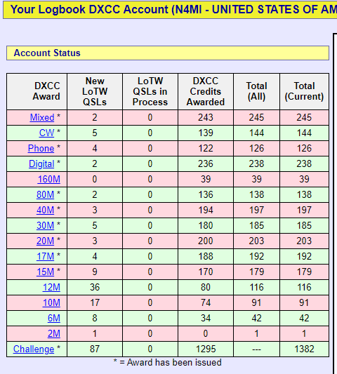
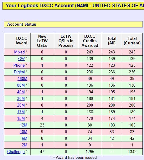
A few good FT8 and FT4 QSOs on 20 and 30 metersVR2XRW confirmed our QSO on Logtbook of the World within minutes!N1ADM’s DXCC Account Status as of August 15th, 2020
Accurate computer time is absolutely essential for successful QSOs using digital modes such as FT8, FT4 and JS8. While millisecond accuracy is not necessary, if the computer clock is off by more than a second, you are likely to experience problems. It is very easy to check the accuracy of your computer’s clock by using the website time.is.
A check of my computer’s clock on time.is showed that it was 0.3 seconds behind. This is well within specs for digital modes.
Recent versions of Windows will frequently update the clock through time servers, but the updates are not usually as frequent or accurate as I would like. There are also several applications that will connect to Internet time servers to periodically update the computer clock. Some examples are Meinburg NTP, BktimeSynch, Dimension 4, and NetTime. I have Dimension 4 loaded on my shack computer.
Dimension 4 periodically updates the computer clock using a low level internet protocol, called SNTP, to connect with special purpose Internet Time Servers.
But what if you don’t have Internet access, due to an outage or working in the field? Fortunately, there are computer applications that will synchronize your clock using GPS signals. To do this, you need the software and a GPS receiver for the computer.
For my computer, I use a GlobalSat BU-353-S4 USB GPS Receiver and NMEATime2 software for GPS-PC time synchronization. The GPS receiver cost me $34, and it also cost me $20 to register the software.
The GPS receiver connects to a USB port on the computer as a serial device. I have the receiver in a windowsill near the computer.
On my computer, the GPS receiver is the Prolific USB-to-Serial Comm Port (COM4).
After the GPS receiver, I installed the NMEATime2 software. It was very easy to set up the software to work with the GPS receiver. Once installed, the software runs in the background to keep the computer clock updated. There is an icon in the system tray that shows the current status.
The green satellite icon in the system tray indicates that NMEATime2 has a good GPS signal lock and the application is disciplining the computer clock.
A right click on the tray icon and selecting “Show Panel” will bring up the software control panel with menus for settings and four tabs: Status, GPS Status, Loop Status, and NMEA Output. For my purposes, the Status panel and GPS Status panel contain the most important information.
The Status panel shows the current time and overall quality of the GPS satellite signals.The GPS Status panel shows which GPS satellite signals are being received, and the signal quality for each, as well as location information.The Loop Status tab displays the status of digital filters that filter out any spikes or outliers before sending the filtered signal to the application’s control algorithm.The NMEA Output tab displays the NMEA data strings as they are received from the satellites.While running NMEATime2, my computer time is usually exact or very close.