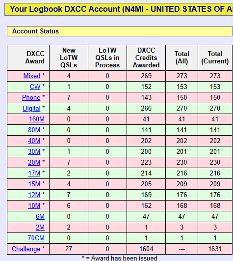
I have been working a lot more SSB since I added the hexbeam and amplifier to the station. The majority of my confirmed DXCCs has been on digital modes FT8, and before that JT65), so I have been making more of an effort to confirm DXCCs on CW and phone. DXpeditions over the past few months have helped tremendously. I have reached 273 DXCCs on LoTW, so the going will be very tough from here. Hopefully I can continue to add to the CW and phone totals!
My preferred logging software is N3FJP’s Amateur Contact Log. It is easy to use, and integrates well with my IC-7610, and with WSJT-x/JTAlert. It can also automatically upload contacts to several online logging/QSL platforms (LoTW, QRZ, CLubLog, and eQSL). I have been very happy with this workflow, and it covers my logging and verification needs.
At the recommendation of a trusted friend, I decided to check out World Radio League (WRL). It is a cloud-based application that is sort of a mashup of a logbook and social networking for ham radio operators. The team that designed and built the application also created Ham Radio Prep, which is a web-based application that prepares hams for license exams.
WRL is available as a web application, as well as apps for Android and Apple phones and tablets. You can sign up for WRL for free, with limited features. There are also three paid levels (Basic, Premium, and VIP) that offer more features and capabilities. I chose the Premium level for $60/year.
I have only started to explore the options in the WRL web application. I was able to create a profile with my station information, and uploaded an ADIF file (from ACLog) with all of my contacts. Those two processes went smoothly.
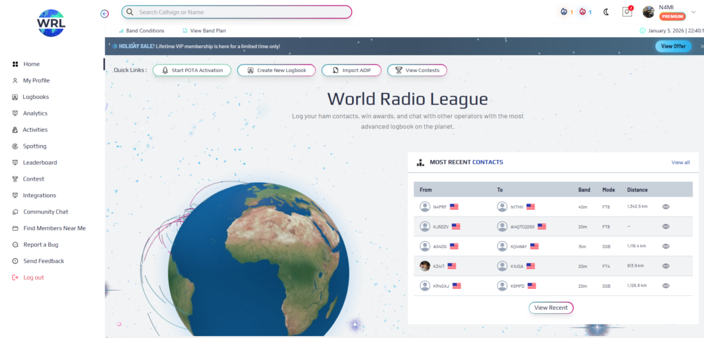
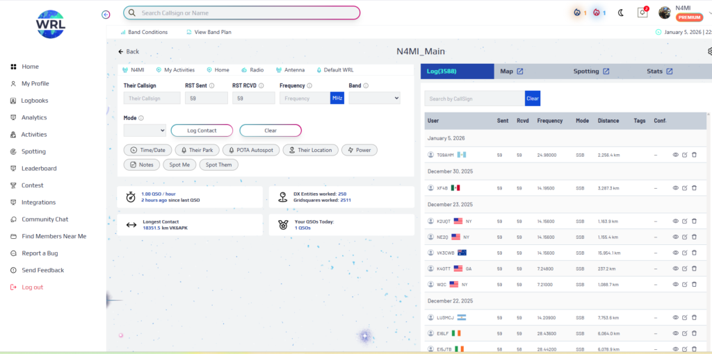
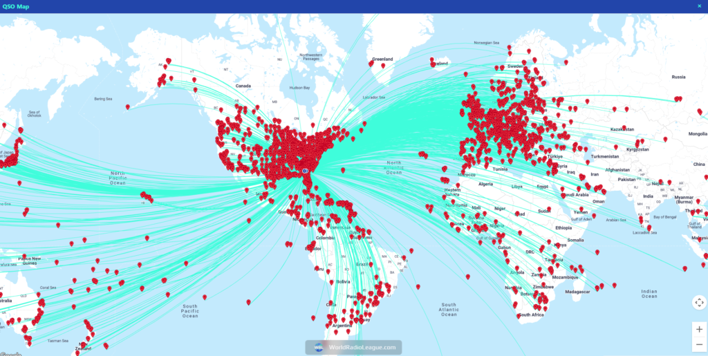
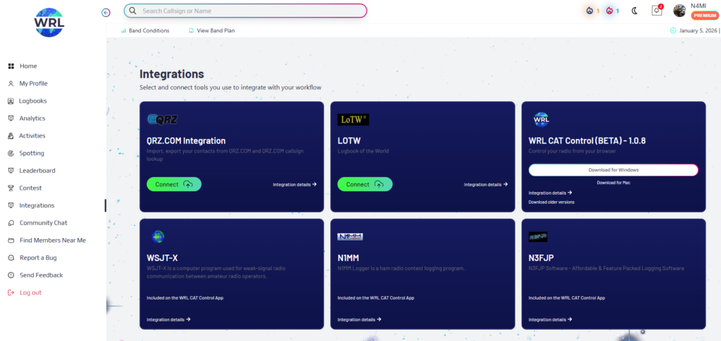
Here are a few screenshots showing some of the key pages and features in the WRL web app:
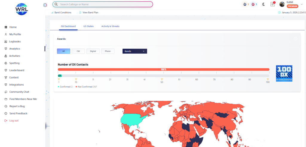
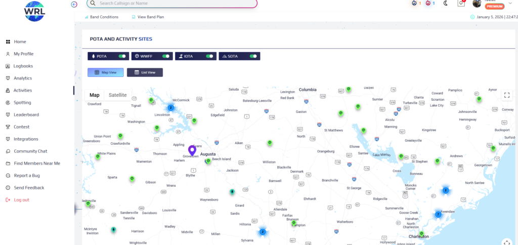
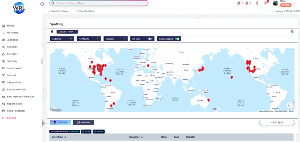
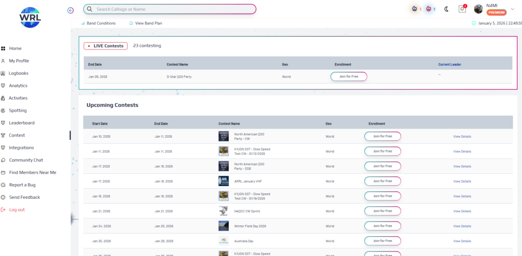
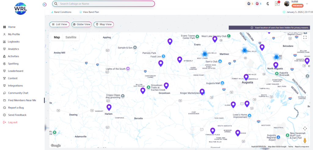
This is the home screen that is displayed after logging in to WRL.This is the logbook page in the web app.The logbook page includes a map depicting the logged contacts.The Analytics page displays all of the countries and states I have worked. It appears that the confirmations only include those from within WRL.The Activities page shows a map or list of POTA, SOTA, IOTA, and WWF sites.The Spotting page includes a very customizable map and list of live spots.The Contests page is very interesting. The app can create logbooks for various contests. The page shows current and upcoming contests, and allows you to “enroll” to create a logbook for the contest.The Integrations page is for setting up and configuring integration with QRZ.com and LoTW sites, WSJT-X, N1MM, and N3FJP.The Find Members Near Me page shows locations (not exact) of other WRL members.
Each of the pages on the web app have a multitude of configurations and display options. There are also several other functions that I haven’t explored yet. I also need to check out the app on my tablet and phone. Time will tell whether WRL will replace any of the other applications in my workflow, or supplement them. I’ll post an update after digging deeper into WRL.
Just for fun, I took drone footage showing the view from the top of the tower. To get the video, I used a DJI Mini 4K drone, and did some light editing in Microsoft Clipchamp. I am still learning to fly the drone and edit videos. This is a first attempt, and hopefully I will get better with more experience.
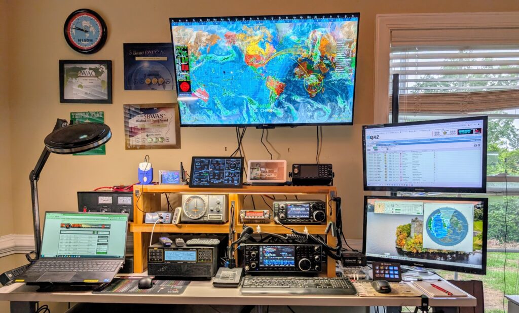
It has been a long journey, but I have finally completed all of the station updates that were started over a year ago. Several of my ham friends came over to pull coaxial cables through conduit, connect coax to the entry panel, and align the rotator. I had some additional work inside the shack to set up a new amplifier and computer. After double-checking every connection and configuration, everything is working great and I am very happy with my (mostly) new station!
Outside I have a U.S. Tower MA-40 tower with Yaesu G-800DXA rotator turning a K4KIO hexbeam antenna with elements for 20-6M. I also have a MyAntennas 80-10M end-fed halfwave antenna, and a discone antenna for my scanner. These are all fed through underground conduit to a KF7P entry panel with Morgan Systems lightning arrestors for the coaxial and rotator cables.
Inside the shack, my station consists of a Icom IC-7610 transceiver and SPE Expert 1.5K-FA Taurus amplifier for HF. For CW, I use a UR5CDX paddle with a WinKeyer USB and MRP40 decoder software. For digital, I primarily use WSJT-X, but sometimes dabble in RTTY and other digital modes. I have a ERC Mini DX as a USB interface with the Yaesu control box, along with PstRotatorAZ software.
For VHF and UHF I have an Icom IC-97oo, as well as an Alinco DR-06TA for use on the local 6M repeater. I use a Uniden SDS-200 scanner to monitor various communication in the local area.
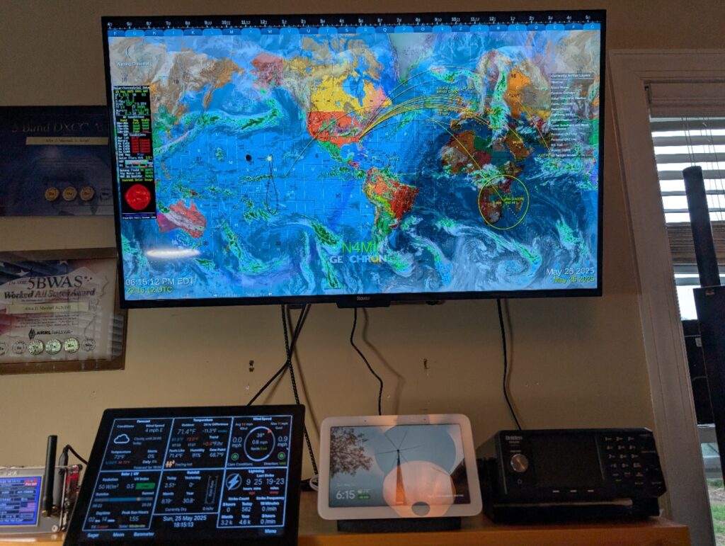
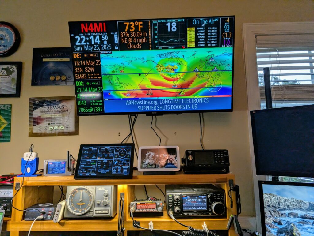
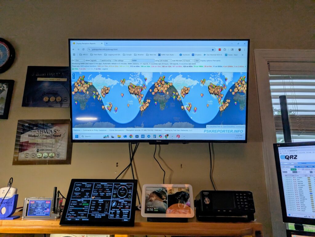
I also updated the TV I had over my station with a 43″ 4K Smart TV. It has 4 HDMI inputs so I can switch between displaying GeoChron and HamClock, or as a third monitor for the computer. I upgraded my trusty Windows 10 shack computer with a new Windows 11 computer. I have Raspberry Pi touchscreen display running WeatherFlow PiConsole software to display weather data from a WeatherFlow Tempest station. I have two MMDVMs, an OpenSpot 4 Pro and a TGIFSPOT 3.5 inch Nextion. Finally, there is a Google Nest Hub that I use as a photo frame and for streaming music and monitoring security cameras.
At Orlando HamCation, I ran across the booth for Spec5. They sell some very cool Meshtastic devices. I briefly experimented with Meshtastic a couple of years ago, but it had not really taken off in my area, so I didn’t get very far. More recently, several people in the area have installed nodes, so it is more interesting and useful now. In fact, there is a group working to install nodes to connect communities across the region. This will make Meshtastic more useful as an option for grid-down communication.
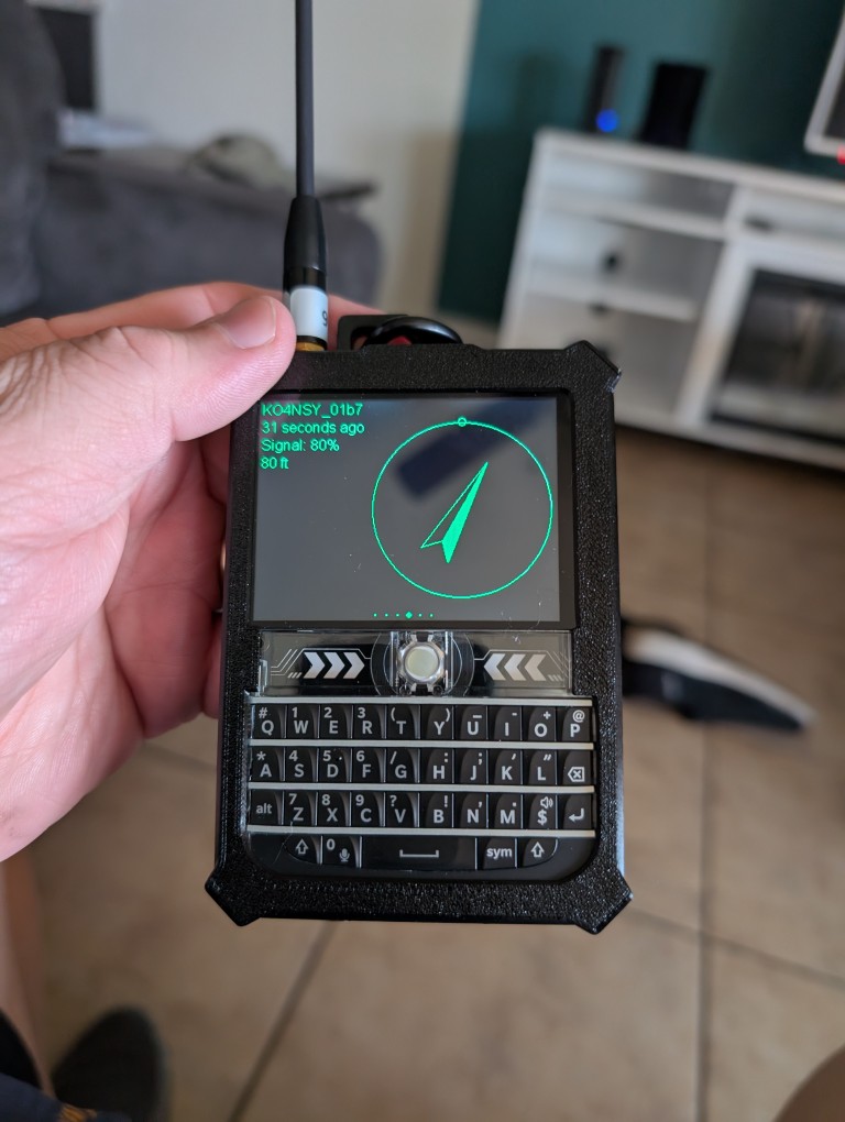
One of the devices I bought at HamCation is the Spec5 Ranger. It is a cool Meshtastic device with a keyboard, so messages can be sent directly through the device. You do need a phone, tablet or computer to configure it initially, but once it is set up it can be used alone.
I had this homebuilt Meshtastic device from my earlier experimentation, so I flashed it with the most recent firmware and configured it with my phone. This one does require a bluetooth connection to a phone or tablet to send messages. It is a LILYGO T-Beam ESP32 LoRa board with OLED display and 18650 battery.
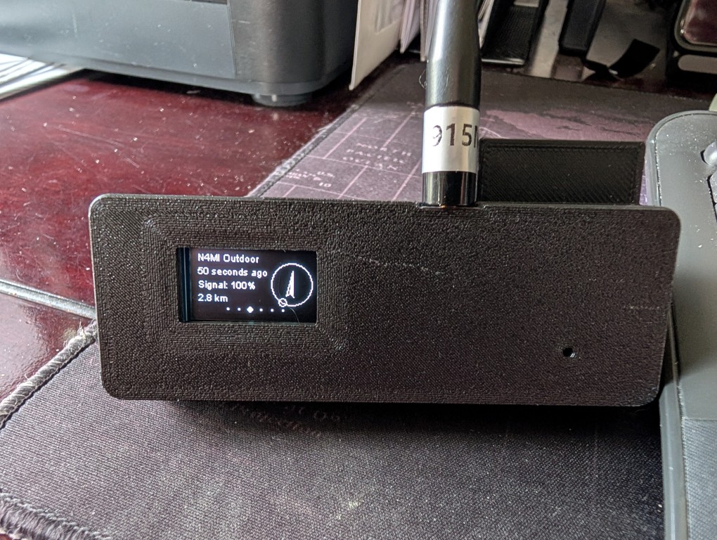
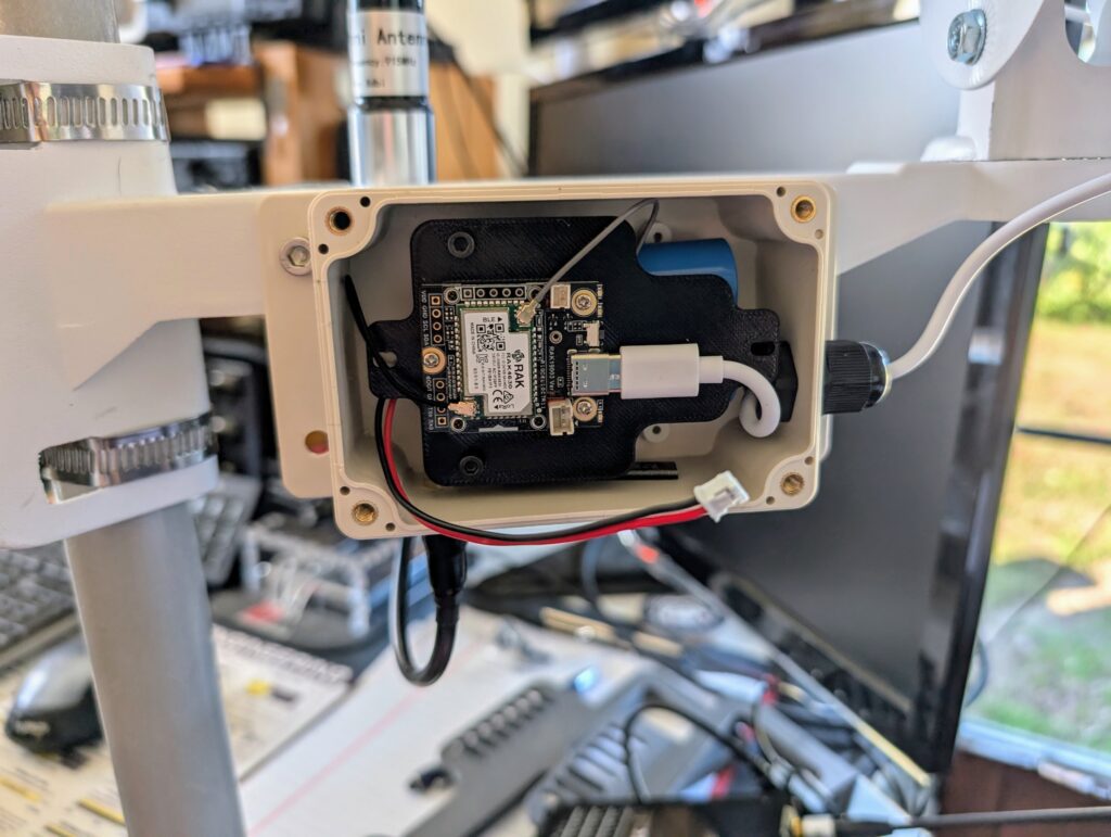
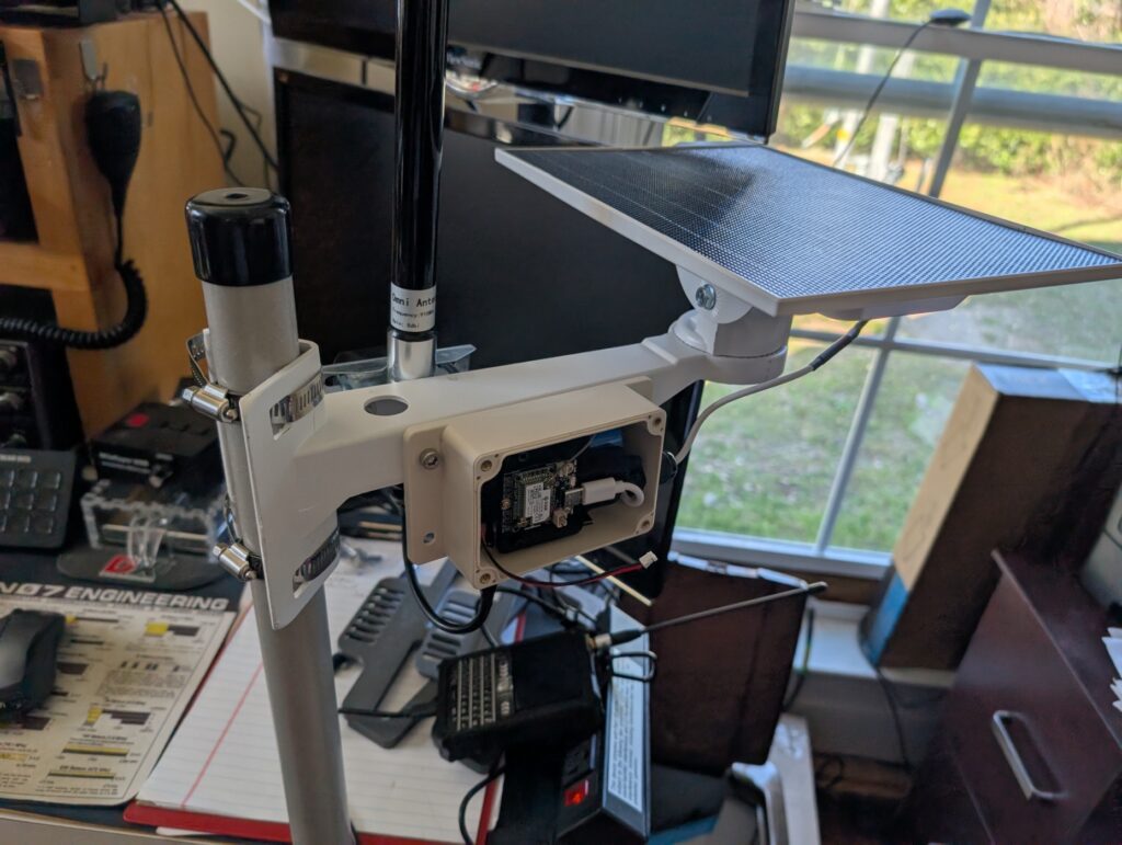
I knew I would have limited range with the handheld devices and small 915 MHz antennas, so I wanted something that could extend the range. I ended up getting another Spec5 device, the Spec5 Relay to set up outside. It was very easy to assemble, and also easy to configure using the Meshtastic application on my phone. I have it mounted on a 15 foot mast at the edge of my property. It transmits and receives over a greater distance due to the better antenna, and placement outside. It has a solar panel to keep the 18650 batteries charged. I will be putting it on a 25 foot mast soon to extend the range even further. While the Relay can be set up in a repeater mode, I have it set up in client mode, which is the best setting for this location.
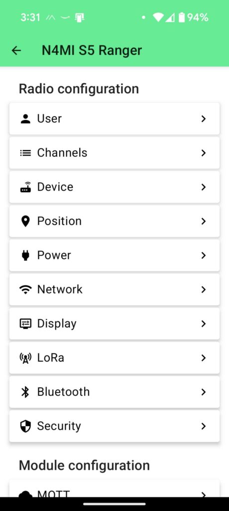
This is a screenshot from the Meshtastic Android app on my Google Pixel phone It is connected to my S5 Ranger by bluetooth. This is a view of all of the different configuration settings.
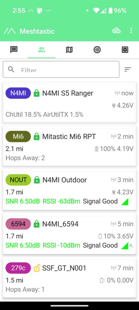
This is a view of the most recently connected nodes that my device can see. You can see my other two device on there (they are very close), but through the S5 Relay it is connected to several other nodes that are further away.
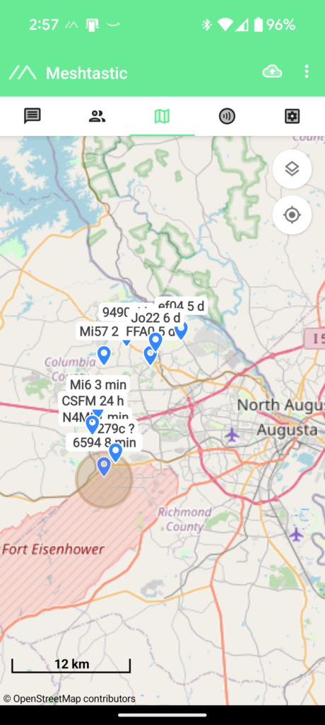
This is the map view from the Meshtastic application, showing several nodes that my S5 has seen from my house and while traveling around the area.
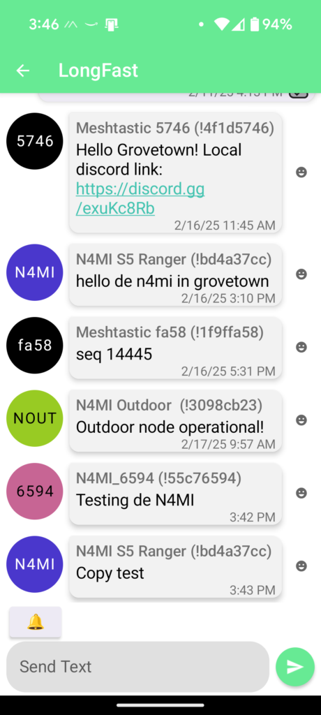
This view shows messages that have been received by and sent from my nodes.
I have one of my nodes connected to an old iPhone. The iPhone Meshtastic app seems to be functionally the same as the Android app, but it looks different.
So, what’s next. I will continue to learn more about the functions and utility of Meshtastic, and will try to help local users extend the mesh to reach more communities.
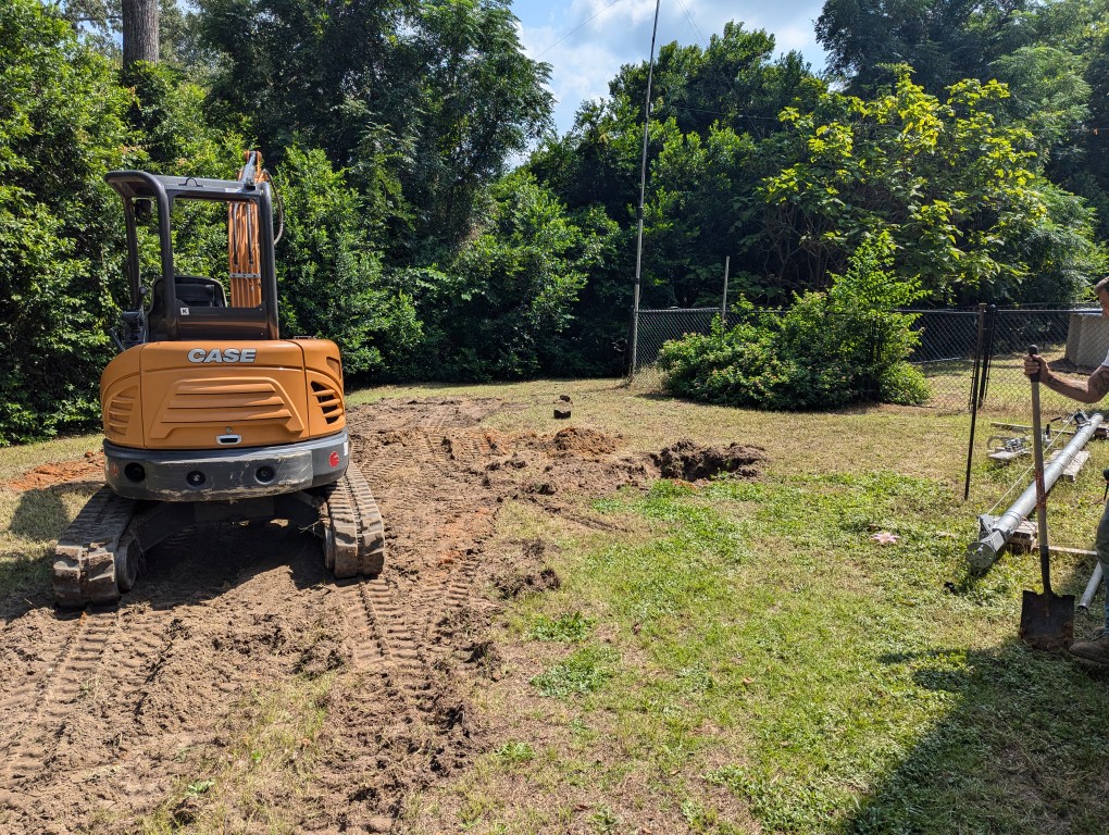
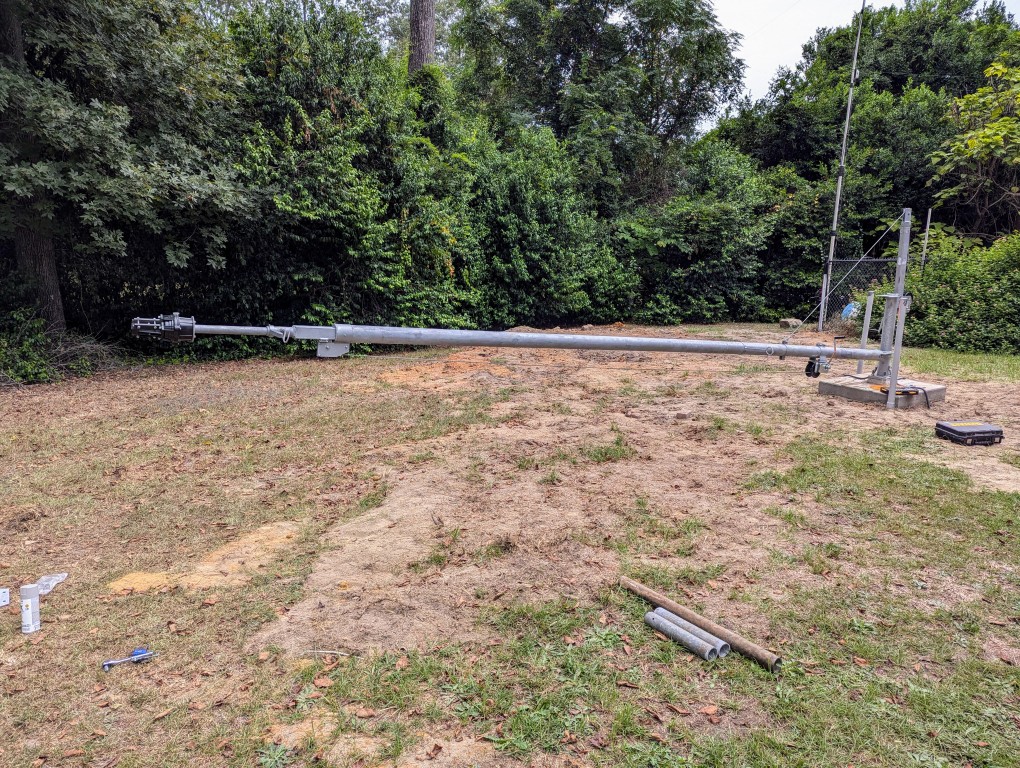
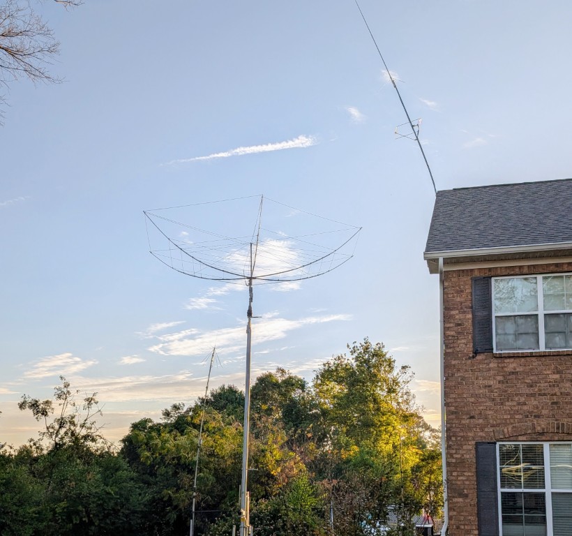
I have not posted any updates for a long time. Since my last post, the new tower has been raised. There is still some work to do. Mainly, running the cable and installing an entry panel. There was steady progress until hurricane Helene came through our area at the end of August. Here are some pictures of the construction and the finished tower. Most of the construction took place during the Summer of 2024.
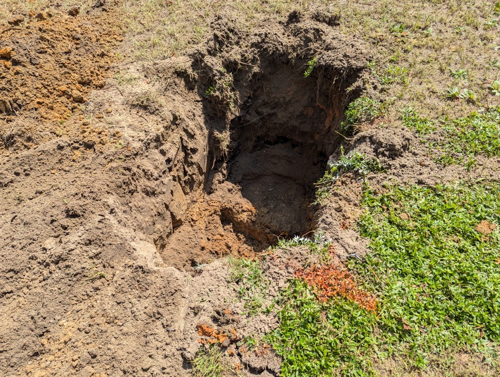
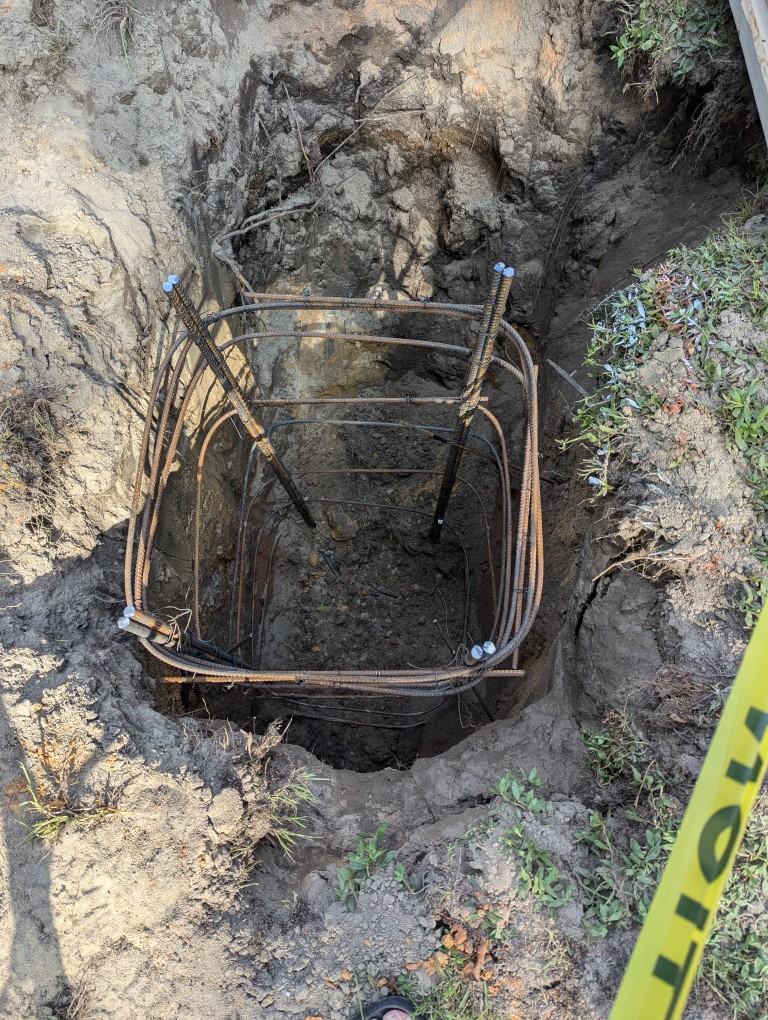
It all starts with digging a hole. This one is 5 feet deep by 3 feet wide.
After the hole was dug, the rebar cage went in.
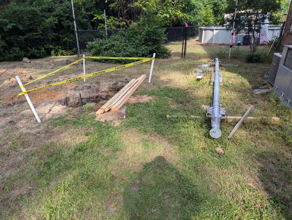
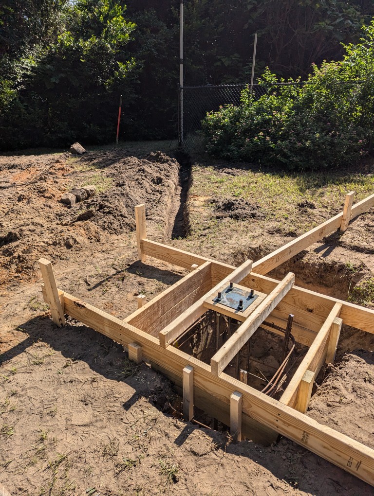
The forms for the concrete base were then added. I also added some trenches to lay conduit for coax. I have a wire antenna on the mast at the fence. The conduit will route that coax to the tower, then coax from all antennas will come from the tower to an entry panel at the shack.
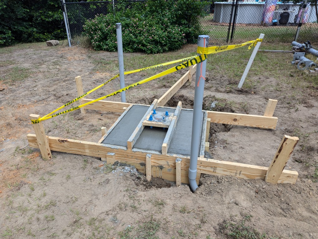
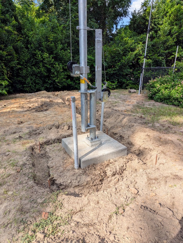
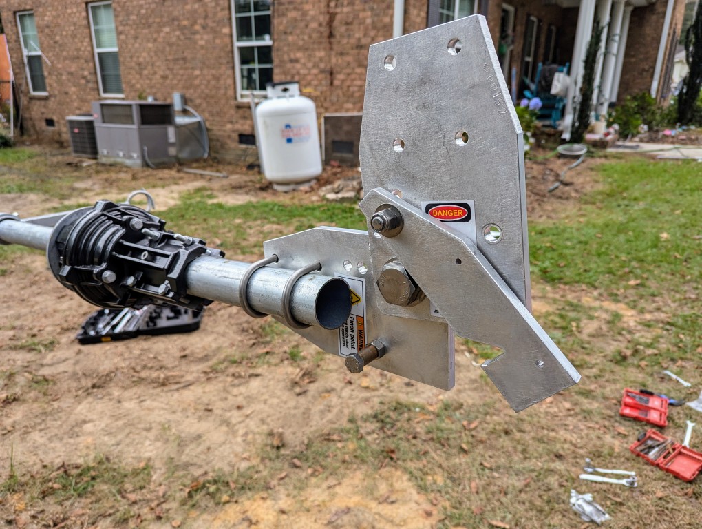
The concrete for the foundation was poured, and after a few days of curing, the tilt base and tower were bolted onto the foundation.
Then the rotator and a tilt plate for the hexbeam were installed onto the tower.
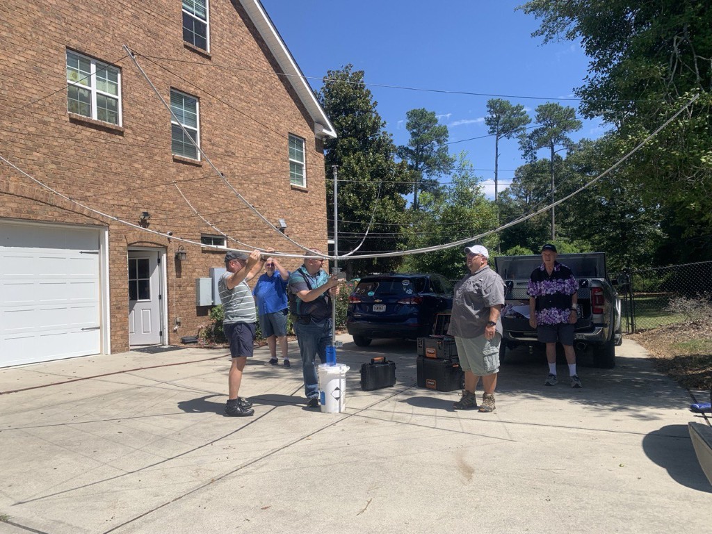
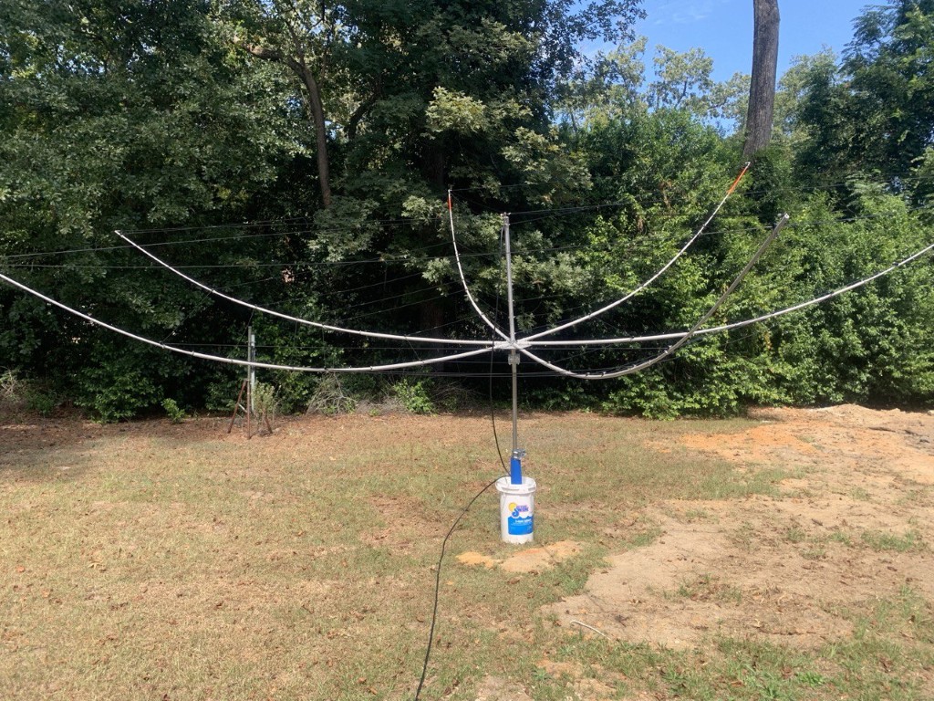
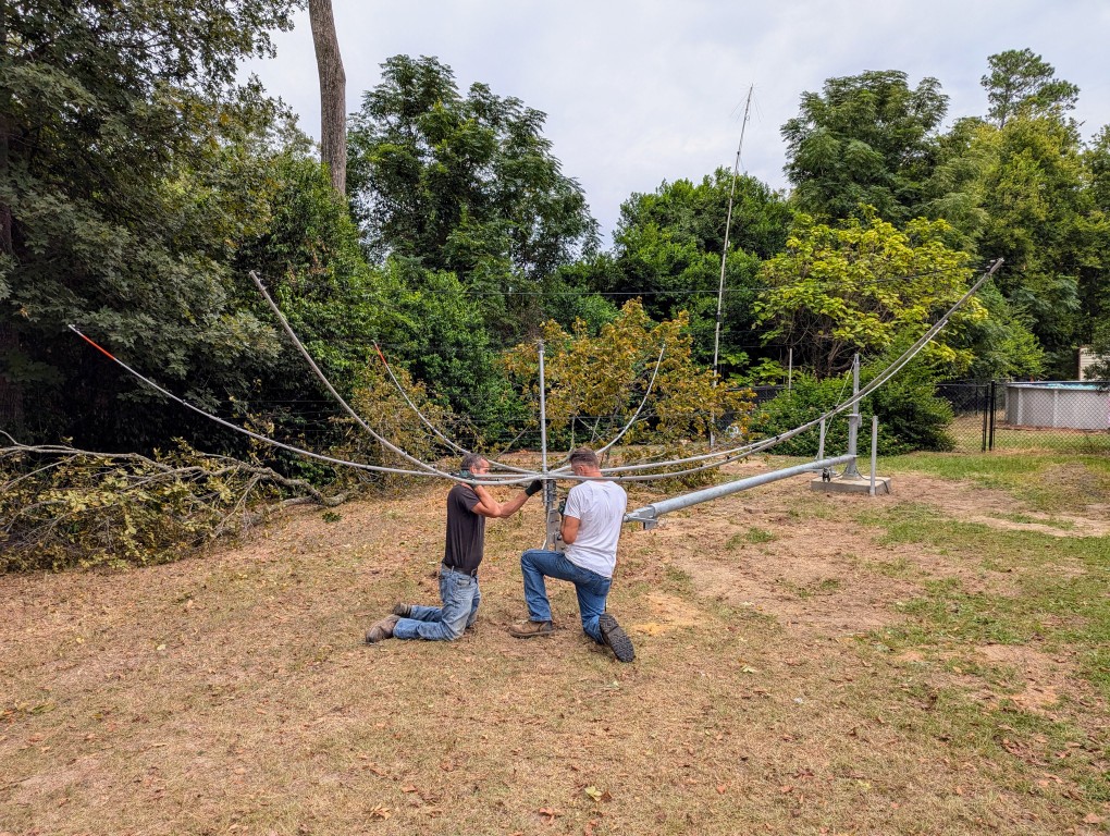
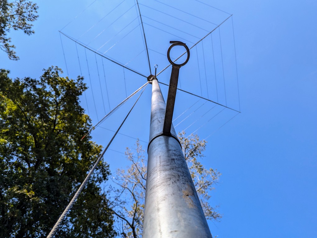
Several friends came over for an antenna party to build the hexbeam.
After it was built, we tested the SWR and it was excellent on all bands, 20M to 6M.
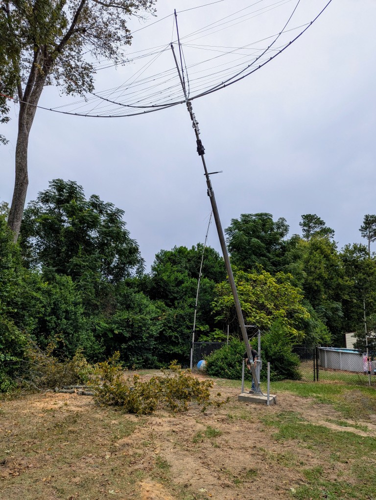
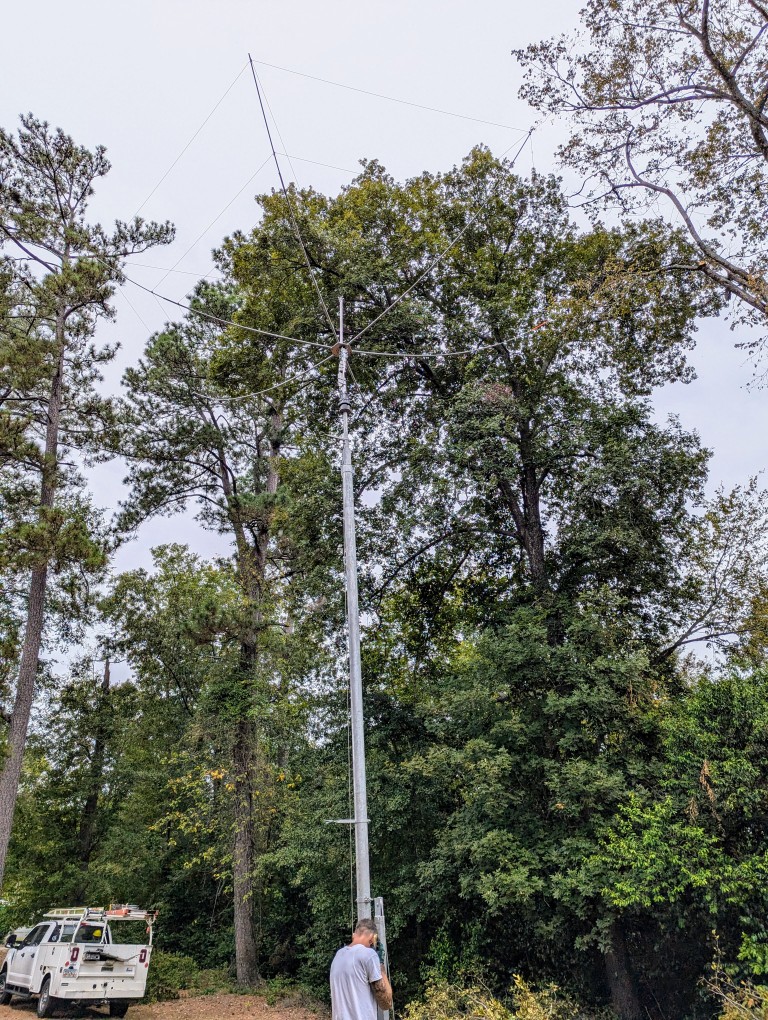
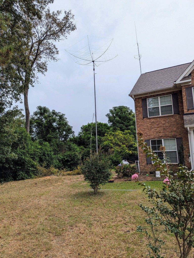
A few days later, the hexbeam was attached to the rotator, and the tower and antenna were raised.
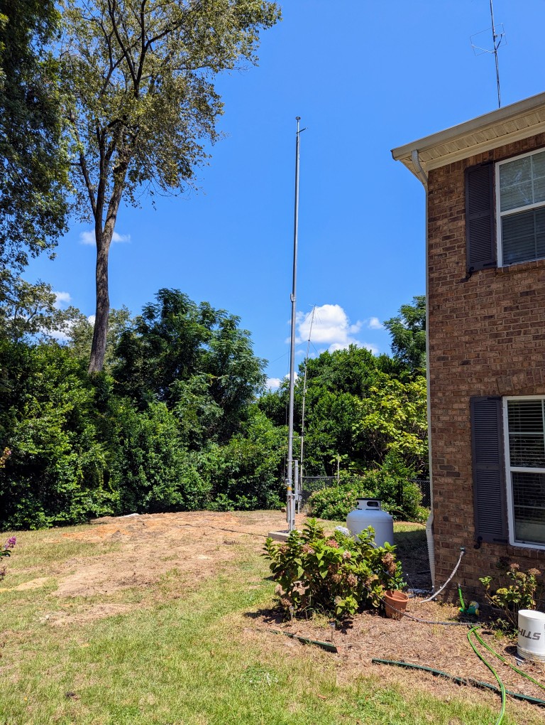
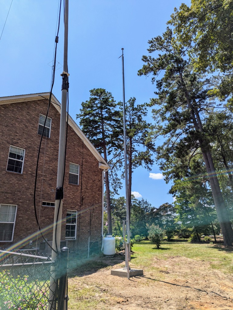
I mentioned that hurricane Helene introduced some delays in finishing the project. I had the tower fully lowered. The hurricane force winds came from the south, and the tower is on the north side of the house, so the tower and hexbeam were not damage. The biggest holdup is that the winds bent the mast and the eave mount for my VHF/UHF vertical on the roof of my house. The vertical is now hanging over too far for me to fully raise the tower. I need to get a lift to either remove or repair the vertical mount.
I also still need to install the entry panel, which will involve drilling through the wall to route the coax from the panel into the shack. I hope to get those things done in the next few weeks.
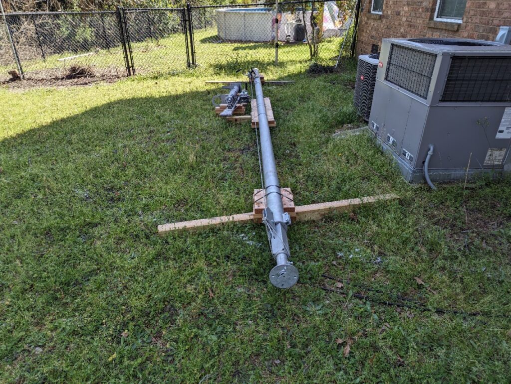
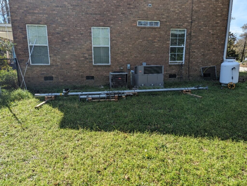
I recently purchased a U.S. Tower MA40 crank-up tubular tower. The ordering process through the Ham Radio Outlet store in Atlanta was fairly easy and straightforward. I was told there could be a 20+ week lead time when I ordered it, but it arrived earlier than expected. If you are considering buying a new tower, be sure to include the cost of freight in your expense calculations. The cost of freight from California to Georgia was close to a third of the price of the tower itself.
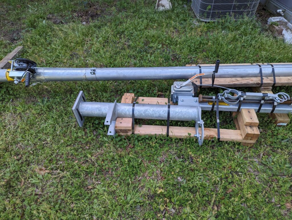
This is a relatively small free-standing tower at 40 ft high, and it’s really more of a super heavy-duty mast. It can be cranked down to 21 ft in the event of high winds or bad weather. I also bought the MAB-40 tilt-over base, which will allow the tower to be completely lowered for very bad conditions or to perform maintenance on the antenna or rotator.
I will be using a K4KIO hexbeam antenna with elements for 20M through 6M, and a Yaesu G-1000DXA rotator. I also need to start work on an entry panel with lightning protection for the coax and rotator cables. I will also route the cables for my existing wire antennas through the entry panel, and leave room for a few more.
I am very excited about the significant improvement the tower and antenna will make to my station. It will take some time to get the tower installed. The town I live in requires a Conditional Use Permit to install any type of tower on residential property. It definitely pays to learn about the municipal codes in your jurisdiction when planning to install a tower. I received some excellent advice through the ARRL Volunteer Counsel program. Fortunately, the Planning Department is supportive and giving me a lot of help to prepare the application, but the soonest it can be presented to the Board of Zoning Appeals is June.
For now, the tower is resting peacefully on the ground at the side of my house. There’s lots of work still to do, but I am getting closer to my dream of adding a directional antenna to the shack! More to follow as this project progresses.
I have been learning about how to use ChatGPT and some other AI models to enhance my participation in the Amateur Radio hobby. I am also starting to learn how to code in Python, to hopefully create some code that will be useful to me in the hobby. ChatGPT is especially helpful for learning Python and optimizing code.
Just for fun, I started using the image generation models in Dall-E to make some interesting pictures featuring my Louisiana Catahoula Leopard Dog sidekick Luke. Here are a couple that turned out really well. They don’t look exactly like Luke, but they are amazingly good for pictures created only with word prompts.
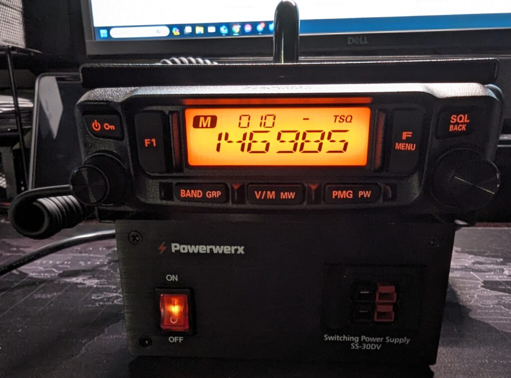
I decided to build a small 50W VHF/UHF station to use for portable operations, such as supporting events or setting up in a temporary location, with a choice of using AC power or a battery. I don’t need anything fancy like DMR or D-Star, but I might want to to use it for APRS or WinLink.
After a bit of research and pricing options, I went with something that turned out to be a very easy build. I chose a Yaesu FTM-6000R as the transceiver. It has basic features, but has gotten some good reviews. It is also known to be a good transceiver for data, and is 9600 bps capable.
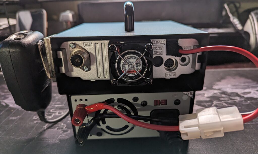
I also chose a 30 amp switching power supply and a mobile base station enclosure from PowerWerx, to make it a single unit that’s easy to carry around. The enclosure includes a short DC cable to connect the radio to the power supply. If I want to use a battery instead of the power supply, I just disconnect the T-connector from the power supply, and connect it to the battery. It was very easy to assemble the whole system.
I tested with the power supply and with a battery, and it works great. The whole unit is very compact and stable.
My next step will be to configure it for WinLink and APRS. I have a Mobilinkd TNC-4, and I ordered a DigiRig. The FTM-6000R has a 10 pin MiniDin connector, and DigiRig sells 1200 bps and 9600 bps cables for the radio. DigiRig also sells an adapter cable to use DigiRig cables with a Mobilinkd, and vice versa.
I’ll make another post after testing the setup with WinLink and APRS.
I’m working on some significant upgrades to my ham radio station. I finally received a Mercury IIIs amplifier. I was on the waiting list for about a year. I also got a Palstar HF Auto tuner to handle the increased power from the amp. For outside the shack I also got a K4KIO Hexbeam antenna. The only problem is that I don’t have a tower for it yet. That will be next, and hopefully soon! I’ll make additional posts as I bring the new equipment online.