My faithful old 2011 Tundra pickup truck, as great as it was, was starting to require frequent repairs. I got a great trade-in offer for it, so I got a new Dodge 1500 Crew Cab. A new truck means time to install a new radio! My good friends Rusty KG4HIR, Randall KN4FYG, and Steven KN4RVU offered their expertise, time and sweat to help me install the radio. They’ve all had experience with mobile radio installation, but this was my first time.
In my Tundra, I had an Icom ID-5100A, and I had a Kenwood TM-D170GA in my shack. It seemed like a no-brainer to mount the Kenwood radio in the new truck to take advantage of the APRS capabilities, which are not really needed in the shack. So, the ID-5100A from my old truck was moved into the shack, and the TM-D710GA was designated for the new truck.
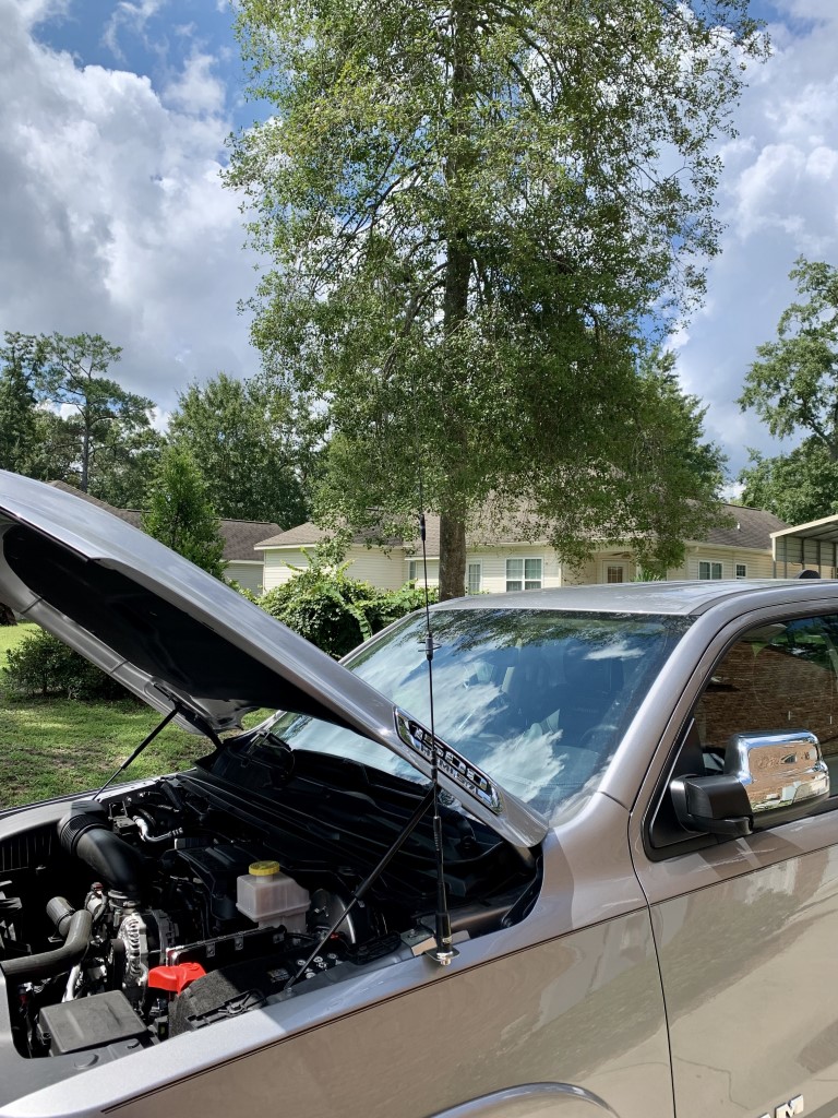
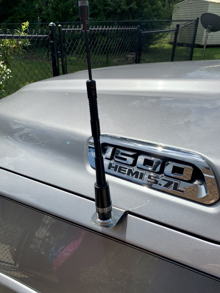
New Ram 1500 pickup with dual band antenna installed on a fender mount.
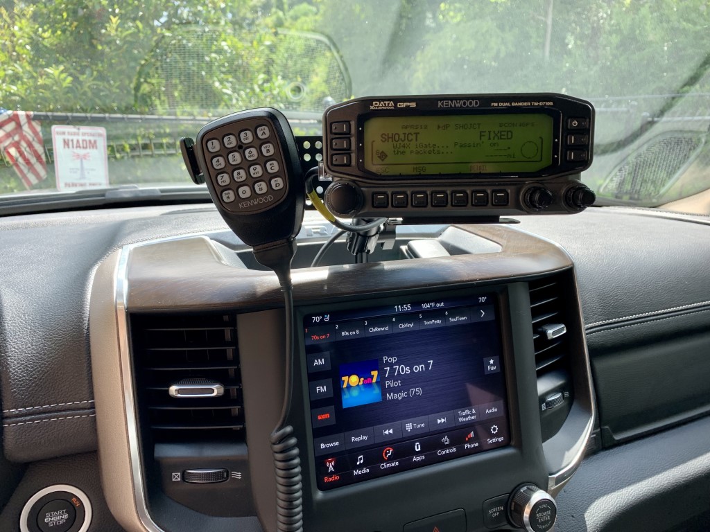
Rusty gave me some good advice, which is to get used to the layout of the new truck before deciding how and where to mount the radio. I did not want to drill too many holes in the new truck, so I decided to go with a fender mount for the antenna. I got an antenna mount, specifically designed for the Ram 1500, from Valley Enterprises. The main unit of the radio is mounted with a bracket under a back seat. After some research, I chose a center dash mount from ProClips, and an extension plate with magnetic puck from Lido Radio for the head unit. The dash mount is very sturdy and well designed. The magnetic puck on the extension plate is very convenient for the microphone.
The install went very well. It was a hot and humid morning, but the awesome install crew got the job done in about 3 hours. All of the truck parts went back in place, with no extra or missing pieces, and the radio powered right up. The way everything is mounted makes it very easy to install a new radio, if that’s ever necessary.
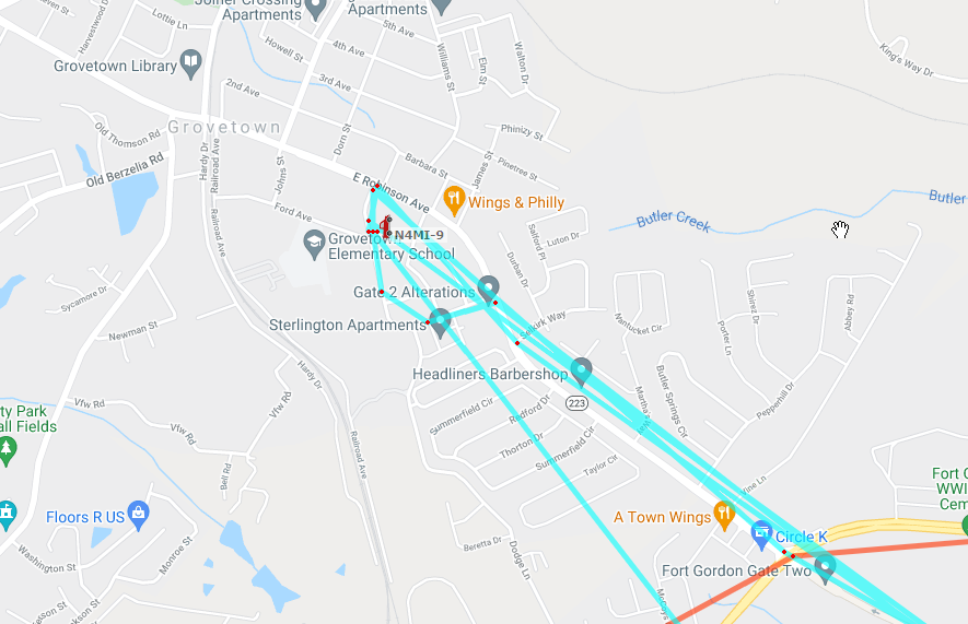
The radio had previously been programmed for use in the shack, but we were able to verify that it was transmitting and receiving. Later, I reprogrammed the radio and adjusted all of the settings for mobile use. I also did some test drives to see how the radio performed with the local repeaters, and simplex with a few friends. It seems to perform as good as I would expect with a fender-mounted antenna. I also have it transmitting APRS beacons as N4MI-9.
I am very pleased with the radio and how it is installed! It’s great to be on the air again while I’m rolling.
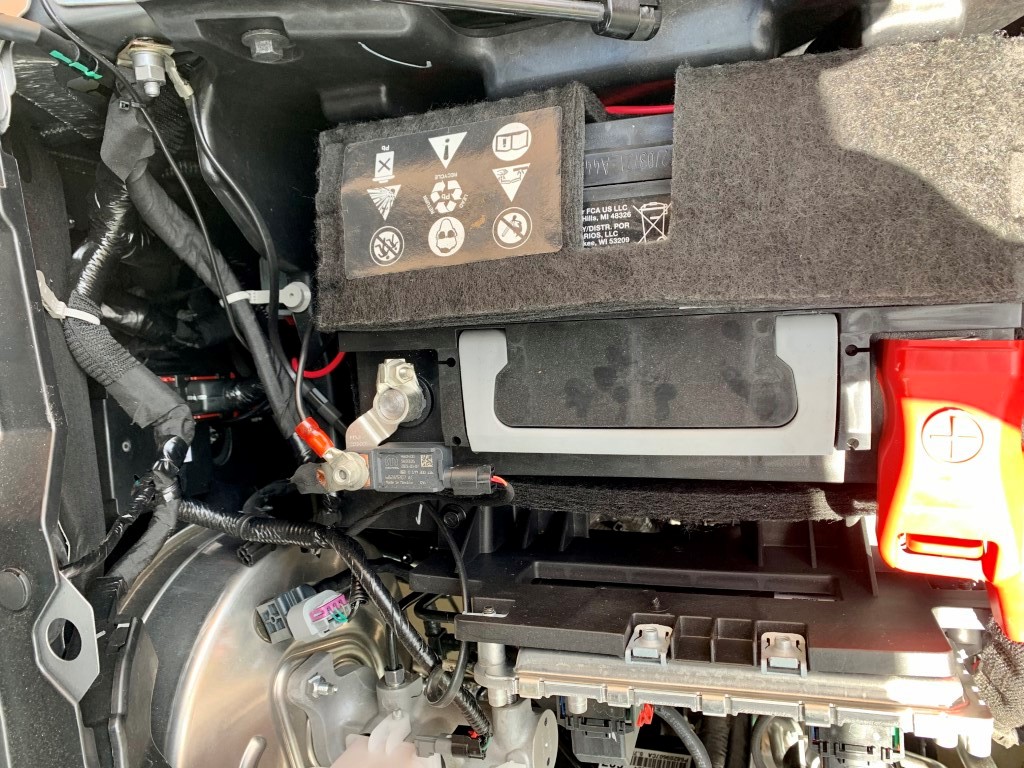
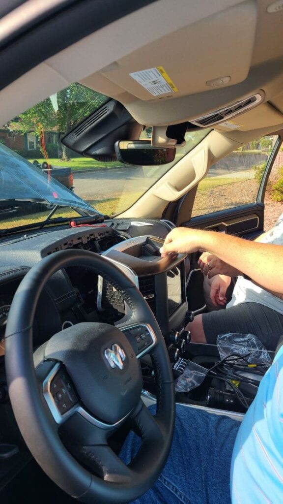
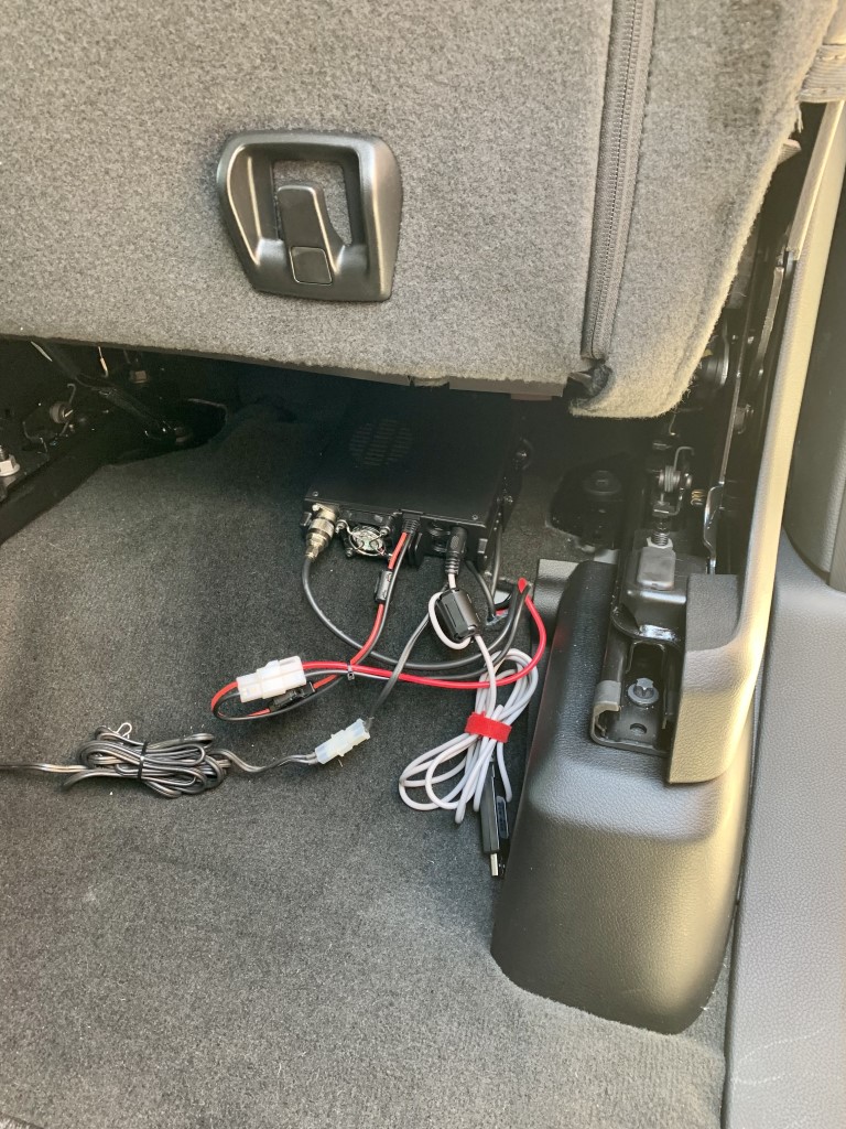
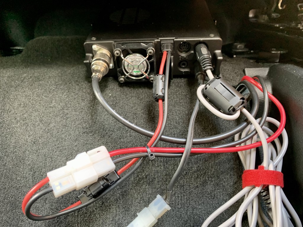
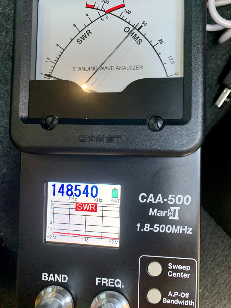
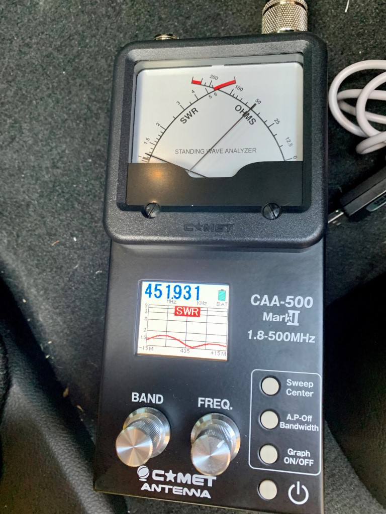
The power and antenna cables came through the firewall with some gentle persuasion, through an existing hole where other wires were routed from the cabin to the engine compartment.Did you know that the center entertainment console just pops out of place with a good tug? It’s held in place with two clips. It’s an uneasy feeling when pulling it loose! The cable from the radio to the remote head unit is routed behind the entertainment console.The main radio unit is mounted under a back seat. It’s mounted with the rear of the unit facing toward the cabin to improve airflow and allow easier access to the plugs and cables. I leave a programming cable plugged in.The drivers side fender mount came from Valley Enterprises. I am using a Comet CA-2X4SR dual band antenna, which is compact and very broad band across 2M and 70cm.Final installation of the head unit. The cable comes in behind the entertainment console. I used a ProClips mount center dash mount designed specifically for a Ram 1500, along with a Lido extension plate for the head unit and a magnetic puck for the microphone.The CA-2X4SR is either a great dummy load, or a well tuned antenna! You can follow my tracks on aprs.fi as N4MI-9
From the time I became licensed, just a little over 5 years ago, I have been using a trusty Diamond X50A antenna mounted on one 5-foot galvanized steel mast on an eave mount, putting the antenna about 4 feet above the roofline. The apex of the roof is approximately 30 feet from the ground. This antenna has served me very well, and with it I could reliably hit most of the repeaters in the area, as well as work stations on simplex up to about 15 miles away. Last year, I added a Cushcraft AR-6 Ringo for 6 meters. When there is a 6M opening, this antenna works OK and I worked quite a few distant stations (see previous posts under the category 6 Meters). However, because of the vertical polarization, I had difficulty working some stations in nearby grids who have horizontally polarized antennas. Also, the Ringo would frequently detune for mysterious reasons. Even though it was mounted on a telescoping mast, it became tiresome to frequently lower and retune it.
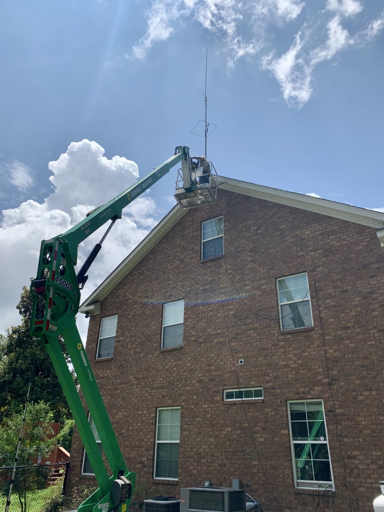
When my friend Rusty inquired about renting a 50-foot articulating boom lift to do some antenna work at his house, I thought now might be a good time to upgrade both antennas. I got a Diamond X300A for 2M/70cm, and a M2 HO Loop for 6M. I also got some new 5-foot galvanized masts and 55-feet of new RG-213 coax. My ham friends came over this morning to remove the existing antennas and install the two new antennas. Special thanks to KG4HIR Rusty, KG4HIQ Earl, W4EFS Walter, and KK4ZHT Eric for working all day on this project in the heat and humidity! Eric and Walter did all of the work in the bucket, and Rusty and Earl did the majority of assembly and adjustment of the antennas on the ground.
For this installation, we used three sections of 5-foot galvanized mast (for a total of 15 feet). Approximately 2 feet of the first section sits below the roof apex in the bottom of the eave mount, so about 13 feet of mast is above the rooftop. The X300A, which is a 10-foot antenna, is mounted on top, and the 6M horizontal loop is mounted about 5 feet below that. We used the existing LMR400 coax for 2M/70cm, and the new RG-213 coax for 6M. We tested the SWR and impedance on both antennas on temporary masts at about 15 feet above ground, and both antennas had great readings as assembled – no need for adjustments. I thought we might have to adjust the 6M antenna once it was in place above the roof, but the SWR stayed about the same at 1.2:1.
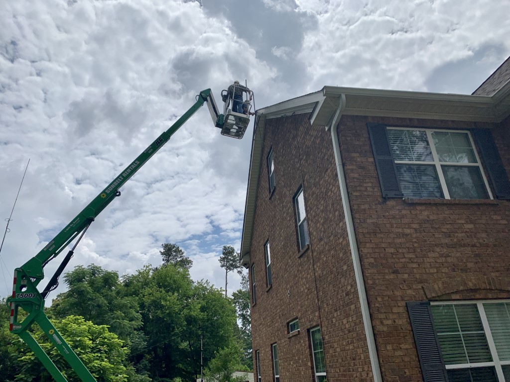
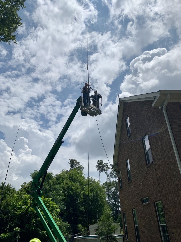
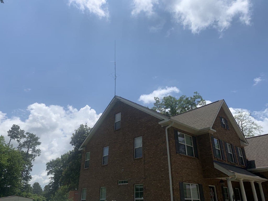
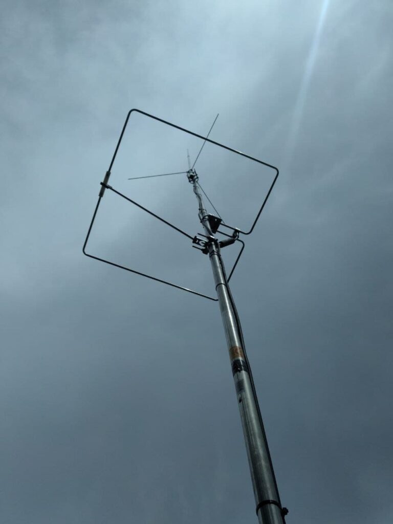
Eric and Walter preparing to remove the existing Diamond X50A and mast from the eave mount. You can also see the 6M Ringo vertical on the left side of this picture.The X50A and the old mast have been removed. Installing the first new mast section into the eave mount.Both new antennas were assembled and mounted to two mast sections on the ground. Eric and Walter preparing to place the two mast sections with the new antennas into the first mast section.All three masts and the two antennas are in place. Walter and Eric are adjusting and tightening all of the mounting hardware.The new masts and antennas in place.Looking up from the roof at the shiny new antennas.
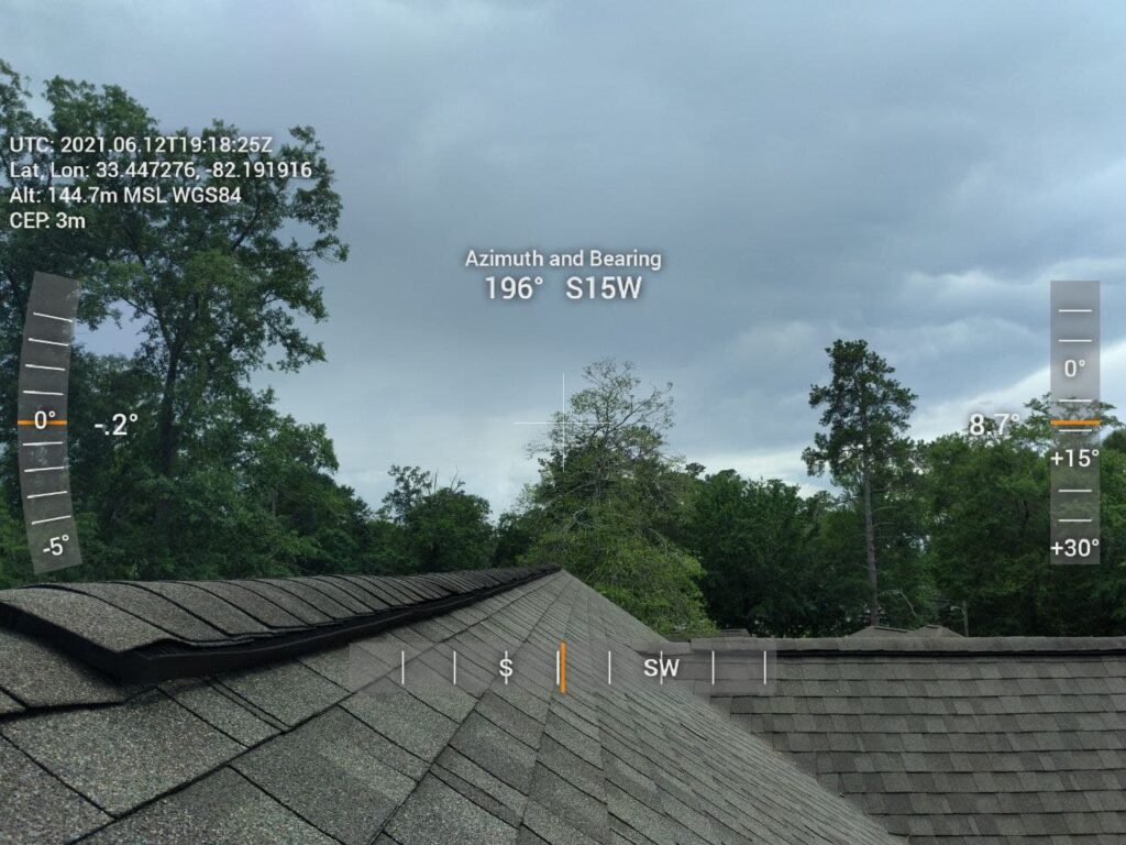
With the lift bucket extended, Eric took some photos that give an “antenna-eye” view from the rooftop.
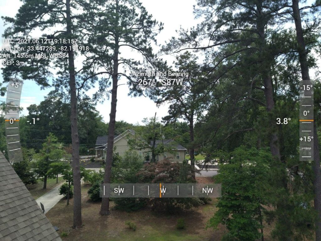
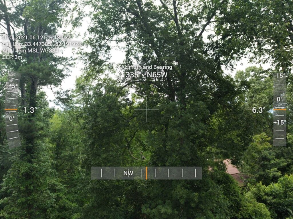
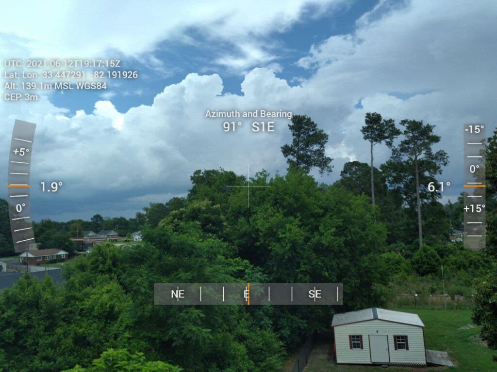
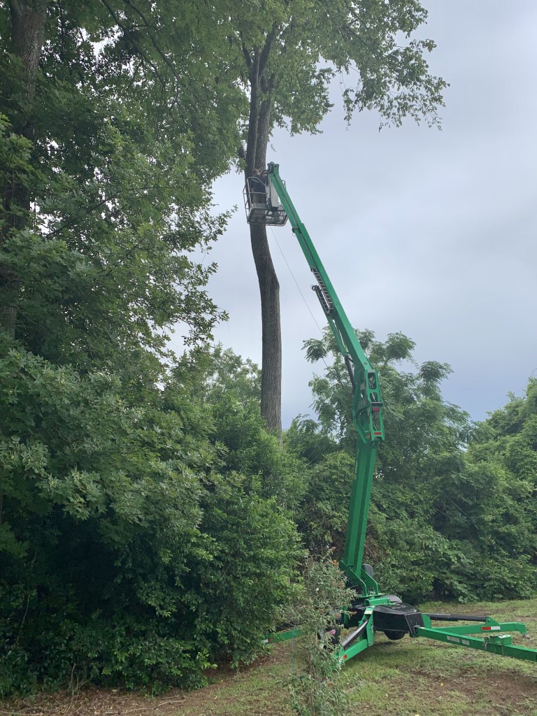
Since we already had the lift, I took advantage of the opportunity to place a couple of ropes and pulleys for future use. The first about 40-45 feet up in a hickory tree, and the other on an old utility pole beside the driveway.
Installing a pulley and rope on a tall hickory tree in my yard.Removing some old wires and installing a rope and pulley at the top of this utility beside my driveway.
We had to take a short break for rain and thunderstorms. (The new antennas survived their first thunderstorm.) Even though there were a few adjustments made along the way, overall the project went as planned and was successful. Unfortunately, we did not have the same luck earlier in the day at Rusty’s house, because we could not get the lift into a position where the bucket would reach his antenna mast. I sure wish that had gone better.
I have not yet had a chance to fully test the performance of the new antennas. The new 2M/70cm has higher gain and is mounted 10 feet higher than the previous antenna. The 6M HO Loop is very narrow-band, but the SWR is nearly perfect at 50.3 MHz, so it will be great for digital and CW work. I did tune to 50.313 MHz and could hear and decode lots of FT8 from stations participating in the ARRL June VHF Contest. I’ll make some additional posts with my observations about the performance as I operate more with these antennas.
WSPR (pronounced “whisper), which stands for “Weak Signal Propagation Reporter,” is a fantastic digital signal for assessing band conditions and evaluating antenna performance. It’s also great for detecting band openings. WSPR mode implements a protocol designed for probing potential propagation paths with low-power transmissions. The protocol was designed, and a program written initially, by Joe Taylor, K1JT. WSPR is included in the WSJT-X software, along with several other weak signal digital modes (FT8, FT4, etc.) for amateur radio. WSJT-X can be used to transmit and receive WSPR signals.
WSJT-X v.2.3.1 receiving and decoding WSPR on 20m.
There may be times when you don’t want to tie up your HF transceiver for WSPR signals, and you really don’t need the power that’s available in most HF transceivers for WSPR. With a decent antenna, you can transmit and decode signals over very long distances with very low power. Because of the encoding of the WSPR signal, a 200 mW signal has the same DX capability as a 1 KW SSB transmitter, or CW at 80W.
You can search the Internet for information on how to build your own transmitter, and there are also some kits for sale. There are also a couple of relatively inexpensive and small WSPR transmitters that are easy to configure and use. I have been using the WSPRlite Classic, made by SOTABEAMS, and two WSPR Desktop Transmitters, made by ZachTek. There are some common features between the two, but there are also quite a few differences. Both transmit a 200 mW signal using 5V (USB) input for power, and both use software for configuring your callsign, location, etc. They can also be powered from a USB power bank.
The WSPRlite and WSPR Desktop transmitter require 5V power and programming through a USB input (micro USB). Both have a SMA connector for the antenna, so a SMA male to PL-259 adapter may be useful for connecting to your antenna.
SOTABEAMS WSPRlite
The first WSPR transmitter I started using is the WSPRlite, which costs around $140. It is very small and light, and therefore great for portable operations. The unit contains internal filters for 20m and 30m, but SOTABEAMS also sells filter kits to expand the capability to include 630m, 160m, 80m, 60m, and 40m. I have not purchased or used any of the filter kits.
The WSPRlite is very small!
A unique feature from SOTABEAMS that comes with the WSPRlite is the DXplorer web site.
The WSPRlite instructions, configuration app, USB drivers, and firmware updates are available on DXplorer. Following the detailed instructions from the website, configuring the WSPRlite is a relatively easy process that involves installing USB drivers and configuration software, connecting to the computer through a USB port, selecting the appropriate COM port, entering data for a few settings, and saving the settings to the device. Once configured, the WSPRlite is ready to transmit. The trickiest part to begin transmitting is pressing a button 2 seconds after the start of an even numbered minute (i.e. 14:58:02, 10:20:02, etc.) to begin transmission. The time must be set accurately for the transmitted signals to be decoded.
Windows Device Manager will display the COM port. The WSPRlite is on COM14.The WSPRlite configuration software is very easy to understand. Enter the callsign, Maidenhed grid locator, band, desired power level (5 mW – 200 mW). There is also a link to the DXplorer site to view statistical analysis of the WSPR signals you transmit.
The configuration application also provides a link to dxplorer.net, where you can view statistics and maps depicting the WSPR signals transmitted from the WSPRlite. There are several different ways to view the data, including a metric call DX10. According to SOTABEAMS:
We use the WSPR data to generate a special metric, DX10. We recalculate your DX10 range (km) every two minutes. DX10 is a great system performance indicator. The best HF system will give the longest DX10 ranges. … Within seconds of your two-minute WSPR transmit period ending, you can see where you have been heard.
The main page for my callsign in DXplorer, with links to view maps, tables, and graphs. You can also change the band and callsign.You will probably want to view the Spots Map first, for a visual representation of where your WSPR signal is being received. It is a zoomable Great Circle map centered on your QTH. WSPR only uses the first part of your locator so your exact QTH could be some tens of kilometers from your actual location. The map shows the location of stations that have received your signal over the selected period. The colors relate to signal levels. You can “mouse-over” the spots to see additional data.The Spots Table provides more details about the stations that decoded your signal. It shows the raw WSPR data for your selected time period. This is useful as it allows you to see all the stations who spot you not just the DX10 list.The DX10 table gives you a snapshot of your system performance. However it does more as it identifies the time ranges for the spots so that you can identify the best times for DX openings. At the bottom of the table is a “DX10 mean” for your 10 spots. If there are less than 10 spots the missing ones are assumed to have a range of 0 km.For the DX10 graph, each data point is calculated from all your spots in the previous hour. The best 10 spots (in terms of range) are used to calculate a DX10 mean. The mean is displayed on a graph which is updated every 2 minutes. The DX10 graph gives a good indication of your system performance and band conditions. You can “mouse-over” the graph to see additional data.
The DXplorer website is where the WSPRlite really shines. It’s easy to use and provides lots of useful informaton.
WSPR Desktop Transmitter
The WSPR Desktop Transmitter from ZachTek also costs $140, and is slightly larger and heavier than the WSPRlite, but has several additional features. The unit includes a GPS receiver and antenna, which can automatically set the location (grid) and control the timing of the transmissions. Once initially configured, this makes operation nearly automatic. Additionally, the latest firmware and software supports Type 3 WSPR Messages. A Type 3 message can transmit a more exact location using six figure Maidenhead reports instead of the regular four figure report, which is especially useful if you use the transmitter in a mobile or portable application with it functioning as tracker.
I am using two transmitters, each designed for operation on different bands. The “Mid” model transmits on 40m, 30m, 20m and 17m. The “High” model transmits 15m, 12m, 10m and 6m.
Note: ZachTek now sells three updated models for this transmitter: – “Low” for 2190m and 630m – “Mid-Plus” for 160m, 80m, 40m, 30m, and 20m – “High-Plus” for 17m,15m, 12m, 10m and 6m You can purchase multiple units at a discount ($254 for a Mid-Plus and High Plus, or $359 for all three models).
WSPT Desktop Transmitter with the GPS antenna.
The WSPR Desktop Transmitter also uses an app for configuration. The documentation web page has links to the configuration software, a quick start guide, and lots of additional details about the transmitter. A USB driver might be required to connect to the computer, and there is a link on ZachTek’s download page. Similar to the WSPRlite, once the device connected to the computer with the micro USB cable, you can determine COM port using Windows Device Manager. You set the serial port (for my computer, COM13) on the Serial Port tab, and click open. After a moment the software will be connected to the device.
The Serial Port tab on the WSPR Transmitter Configuration application.
After the connection is open, the next tab to click is WSPR Beacon. This is where you will enter your callsign, and select the bands. With the GPS antenna connected and placed near a window, you should start seeing the GPS signal quality and a position lock. Once the position is locked, the Maidenhead grid information will fill in automatically. When initially powered up, it might take several minutes to start seeing the satellite positions and get a position lock.
Beacon configuration for the “Mid’ model, to transmit on 40m, 30m, 20m and 17m.Beacon configuration for the “High” model, to transmit on 15m, 12m, 10m, and 6m.
Once the WSPR configuration is complete, click on the Save Settings button, then click on the Boot Configuration tab. In this tab, you can configure the transmitter to start up in WSPR beacon mode. When power is applied, once it achieves a GPS position lock, the unit will automatically start transmitting WSPR beacons, cycling through the bands that were set in the WSPR Beacon tab.
The Boot Configuration tab is for setting up the transmitter to automatically obtain a GPS lock and begin transmitting WSPR when it is powered up.
There is also a Signal Generator mode so the transmitter can be used as a piece of test equipment in your shack. It can output a 23dBm sine wave from 2kHz to 50MHz, depending on model. I have not tested or used this feature.
The WSPR Desktop Transmitter includes a Signal Generator mode
The WSPR Desktop Transmitter does not include access the DXplorer website like the WSPRlite, but you could still use DXplorer standard mode to view statistics for signals transmitted from either device. You can also view maps and data for WSPR signal on the WSPRnet.org website. You can get a free account to access all of the features on WSPRnet.
The Weak Signal Propagation Reporter Network is a group of amateur radio operators using K1JT’s MEPT_JT digital mode to probe radio frequency propagation conditions using very low power (QRP/QRPp) transmissions. The software is open source, and the data collected are available to the public through this site.
http://wsprnet.org/drupal/
Front page of the WSPRnet web site
The Map tab opens a configurable map for a visual representation of where your WSPR signals are being decoded.
Map view on WSPRnet
Scroll down in the map to configure the view. There are several settings that you can use to tailor the information displayed on the map.
Map view configured to show spots for callsign N4MI on 30m over a period of 12 hours.
Click on the Database tab at the top of the web page to display a sorted list of spots. This view can also be configured.
Spots for callsign N4MI on 17mThe Database view can also be configured to filter the data and how the the details are presented.
Final Thoughts
The WSPRlite and WSPR Desktop Transmitter both performed very well. There are some difference in features and operation. For the price, the WSPR Desktop Transmitter offers a few more features and once configured it operates automatically every time it’s powered up. The WSPRlite is very small and easy to carry, and the DXplorer website offers excellent statistics for those tracking propagation conditions or comparing antennas. You can’t go wrong with either option, and your choice would depend upon your operating preferences.
This afternoon I finally got around to building a go-box for HF. I’ve had all of the components for a long time, but just never got around to the build. I would like to thank my friend Rusty, KG4HIR, who did most of the work on this build. This go-box is now ready to operate, but I hesitate to say it has been completed because there is still some empty space in the box to work with!
Here is a list of the primary materials used for this go-box:
Icom IC-7300 MFJ 4230MVP 30A Switching Power Supply with PowerPole Connectors MFJ 939I Autotuner Icom SP-35 External Speaker West Mountain Radio Epic PWRgate West Mountain Radio RIGrunner 4004 USB Mounting Brackets for IC-7300 and Power Supply Heavy Duty Hook and Loop Fastener Roll Gator Case Molded 4U Rack Case Two 1U Rack Mount Shelves 2U Rack Mount Panel Spacer with Venting NEMA 5-15R Plug Adapter with Mounting Holes 3 ft. USB Cable B to B – F/M – Panel Mount USB Extension M6 Terminal Binding Post 10 AWG Red/Black Zip Cord 45A Anderson PowerPole Connectors RG-8X Coax Jumper Cables UHF F-F Bulkhead Adapter Heavy Duty Velcro Strips
This is not intended to be a step-by-step tutorial for the build, but we did capture lots of images to give you an idea of how the go-box was assembled.
Rusty, KG4HIR, did the hard work on this project! Here we have the materials gathered. We had mounting brackets for the radio and power supply, but not for the MFJ autotuner. Rusty is preparing to secure it with heavy duty hook and loop fastener strips.The 4U rack mount case before installing the components.More components used for the go-box: 10 gauge zip cord, zip ties, HF4 to PowerPole adapter, RIGrunner, and Epic PWRgate.The Icom IC-7300Preparing the hook and loop fasteners to secure the MFJ autotuner. In the future, we may create some brackets to secure it better, but the hook and loop fasteners are secure and very strong.The MFJ autotuner and power supply attached to the top of the shelf. The mounting bracket for the IC-7300 is attached to the bottom side of the shelf.The IC-7300 mounting bracket was secured to the bottom of the shelf that also holds the autotuner and power supply.After looking at several configurations, we determined that mounting the PWRgate and RIGrunner upright would be more practical for adding and removing cables. They are secured to a piece of square aluminum tubing that is attached to the rack mount shelf at the back of the case.All of the primary components are secured to the shelves inside the case. For convenience, the primary connections into the go-box (AC power, ground terminal, USB cable to radio, and bulkhead connector for coax) are fitted to a vented panel spacer that is mounted at the top on the back of the case.Beginning the process of making DC power and RF connections inside the go-box.All of the connectors are attached to the vented panel spacer, and it is ready to be secured.Completing all connections for power, tuner, USB, and coax.The back of the (nearly) finished go-box. There is still some available space in the back and front of the case. Some of it will be left for airflow and ventilation, but we are considering whether some additional components could be added.The front of the (nearly) finished go-box. You can see the external speaker and the open space at the center top and right side bottom shelf. We may put a meter in the top space, and create a storage compartment at the bottom.
I was told that a go-box is never really finished, and that there will be changes and additions. The Epic PWRgate in this go-box makes it very versatile. It can be powered by AC via the power supply, as well as by a battery and/or a solar panel.
This build took a little over four hours. Much of that time was spent measuring, aligning, drilling and cutting to attach the components to the shelves and spacer. I still need to add some ferrite beads on several wires and cables. The next step after that is a field test to ensure everything is working properly. (That will be a topic for another post.) Once the testing is complete and it is confirmed to be fully operational, I will use the go-box at club operating events and for casual operating from the tailgate or patio.
The first balloon, which carried a payload with a SPOT Trace GPS tracker and a GoPro camera, was designed climb to an altitude of 70,000 – 100, 000 feet before bursting and falling back to earth. A parachute was attached to the payload so it could return to ground intact for retrieval by a chase crew. We expected the payload to land approximately 50 miles east of the launch site, but the balloon traveled much farther than anticipated. The chase teams scrambled and the payload was successfully retrieved approximately 150 miles from the launch site. The camera captured some amazing images while the balloon was in the stratosphere. Some of the best pictures are featured in the linked news stories.
Photo captured from the high altitude weather balloon shortly after launch. This camera captured lots of amazing images during this balloon flight.One of the many spectacular views captures by the camera on the high-altitude weather balloon.
This post focuses primarily on the second “pico” balloon, which carried only a LightAPRS-WAPRS and WSPR tracker as the payload, and was designed to reach an altitude of approximately 50,000 – 60,000 feet and achieve neutral buoyancy to travel for a much longer period of time. The LightAPRS-W, which is very small, was powered by two small PowerFilm 4.8V solar panels with two 5F 3V supercapacitors. With this power source, the tracker transmits APRS on VHF at .5 to 1 Watt, and WSPR on HF at 10 mW (1/100th of a Watt!).
We spent several days configuring and testing the tracker, using the configuration and programming instructions provided by QRP Labs on GitHub, and following some helpful suggestions in the Tips & Tricks for Pico Balloons wiki. The tracker also had two light wire antennas for APRS (19.4 inches) and 20 meter WSPR (16.6 feet), and a counterpoise (16.6 feet) attached.
Assembled LightAPRS-W tracker with two PowerFilm solar panels and super capacitors. It’s really small and light!
Once assembled, the tracker was easy to configure with an Arduino IDE to load the APRS callsign (K4KNS-11), WSPR callsign (K4KNS), and a few other settings. It’s best to pay very close attention to the instructions and comments in the configuration file! After the loading the configuration, we placed the tracker in the sun to test and listen for APRS and WSPR signals. We were able to confirm that the tracker was transmitting good APRS and WSPR signals. Due to the very low power of the VHF and HF transmitters, we could only confirm local reception. With the tracker stationary and in full sunlight, we noted that the LightAPRS-W transmitted an APRS packet approximately every 5 minutes, and a WSPR signal every 4-6 minutes.
Assembled and configured LightAPRS-W in the sun to test the solar panels and monitor APRS and WSPR signals.APRS received from the LightAPRS-W during testing.Good test of WSPR signal from K4KNS!
It’s one thing to have a good test under controlled conditions, but quite another to achieve success under field conditions. On the day of the launch, the weather was marginal, but within acceptable parameters for a launch. We double checked to ensure the tracker was powered up and transmitting, and tied it to the balloon.
Good test of the APRS signal on launch day!
We had a good launch. The balloon, with the tracker hanging 16.6 feet below the balloon (to accommodate the counterpoise) and trailing a 16.6 foot HF antenna, quickly rose to an altitude above any potential obstructions and began its journey. Within moments, we saw the first APRS positions appear on aprs.fi. A few moments later, using the WSPR Watch iPad app, we saw that the WSPR signal was being received across the U.S.!
The first APRS track for balloon K4KNS-11!The 10 mW WSPR signal was received as far west as Oregon!
It was all going so well! We continued to watch the balloon tracking eastward and climbing, following the same track as the high-altitude balloon that had been launched about a half hour earlier. Then, after about an hour of flight, both the APRS and WSPR signal went off the air. At that time the balloon was 55 miles east of the launch site at an altitude of 37,500 feet.
The track and final position received from K4KNS-11.Location, speed, course, speed, altitude, temperature, pressure and solar cell voltage data from K4KNS-11 exported from aprs.fi.
We’re not sure exactly why the signals were lost, but we do not believe the balloon went down in that location. We are speculating that the tracker may have been damaged due to the high wind speeds on lost power. It is unknown how much farther the balloon might have traveled. Despite the relatively short flight, we did collect some good data for the students at Savannah River Academy to evaluate. We also proved to ourselves that we could successfully launch a balloon and track it with APRS, and that a very weak WSPR signal transmitted from high altitude could be received by stations thousands of miles away!
Map on WSPRnet.org showing stations that received the K4KNS WSPR signal on May 5, 2021.Spot Database for K4KNS on on May 5, 2021 from WSPRnet.org.
Using aprs.fi’s data export tool, we were able to export a KMZ file with the balloon’s tracking data, and use Google Earth to view the full track and altitude changes.
Google Earth map of the track and altitude changes for pico balloon K4KNS-11 on May 5, 2021.
This was an amazing experience! We captured many lessons learned, and we intend to build another more hardened version of the tracker so we can launch another balloon and hopefully track it over a much longer distance and time.
I’m not sure exactly why I did it, but on a whim I decided to apply for for a few 1X2 and 2X1 vanity callsigns in call area 4 that were becoming available. Much to my surprise, yesterday I received a notice that I had been granted a new callsign – N4MI. It was not at the top of the list that I submitted to the FCC, but it turns out this is a great callsign for CW: -. ….- — ..
I did not realize how many things would need to be updated with a new callsign. To name just a few:
ARRL and Logbook of the World VE credentials DMR id D-Star registration Echolink QRZ.com logbook and callsign page Clublog HRDLog.net eQSL DXmaps aprs.fi Reprogram hotspots and D-Star, DMR, APRS radios Updating the name and domain for this website New Email address (if it’s based on your callsign) New QSL cards, shirts, hats, name tags (any physical item with a callsign) New license plate with new callsign WSJT-X, JTAlert, JS8Call, Ham Radio Deluxe, logging programs, Winlink, etc. … and probably several other things I’ll discover later!
If you’re an active ham, when you apply for a new callsign do yourself a favor and make a list of things that will need to be updated ahead of time. Some of these changes are easy, but others are more involved and require time to complete.
I have been casually using DMR, D-STAR and YSF (Yaesu System Fusion) modes for a couple of years, using a ZUMSpot. The ZUMSpot is a small board that sits on a Raspberry Pi Zero W. It incorporates a Multimode Digital Voice Modem (MMDVM) and a 10mW UHF transceiver that operates YSF, DMR, YSF2DMR, D-Star, P25 and NXDN modes. The ZUMSpot uses Pi-Star digital voice software. Pi-Star is a custom, pre-configured SD Card image for the Raspbperry Pi, with configuration and operation performed through a web browser. The Amateur Radio Notes website has an excellent tutorial on setting up and configuring Pi-Star. While the Pi-Star configuration appears daunting at first, it is easy to set up by following the tutorial. There are also several videos on YouTube with instructions for configuring Pi-Star.
A few days ago, I was attempting to update the Pi-Star software and the ZumSpot firmware, but kept seeing errors during the firmware update. After several attempts to update the firmware, the ZumSpot wasn’t operating properly*, so I decided to purchase an openSPOT 3, which is made by SharkRF in Estonia.
The openSPOT3 is a battery powered, portable, standalone digital radio internet gateway (aka hotspot). The openSPOT 3 is also configured through a web interface, but the interface and steps for configuration are different than Pi-Star’s. The openSPOT 3 user manual is a web page that is updated frequently when there are firmware updates or features added to the device. Having learned the basics of DMR, D-STAR, and YSF with the ZUMSpot, I found configuration of the OPENSpot 3 to be fairly easy.
* After I had the openSPOT 3 up and running for a few days, I decided to attempt the ZUMSpot firmware upgrade again. It turns out I had missed a step in my earlier attempts, and this time the update was successful. So now I have two MMDVMs!
Both the ZUMSpot and OpenSPOT 3 are excellent MMDVMs. Both are capable of operating the most popular digital voice modes using a DMR, D-STAR or C4FM radio. Also, they both require a wi-fi connection and are configured through a web interface. The openSPOT 3 is great for portable operations since it has a built-in battery and the configuration web page works very well on a mobile phone web browser. Since the ZUMSpot is based on a Raspberry Pi Zero W, it could also be used portable with a USB power bank. The openSPOT 3 costs a bit more more than the ZUMSpot. There are also many other MMDVMs on the market, including inexpensive generic boards and kits available on Amazon and eBay. Digital voice modes with MMDVMs are a great way to talk to hams from all over the world using a VHF/UHF digital radio and an Internet connection.
The Pi-Star configuration panel is used to enter all of the necessary settings for the MMDVM to operate properly.The Pi-Star Dashboard displays a call log and the current status of the MMDVM.The Pi-Star Administration panel displays some additional status information, and options to change some of the settings for the digital mode currently in use.The openSPOT 3 has a “Quick Setup” page to configure the openSPOT3 with the transceiver and connect to the preferred network.The openSPOT 3 status page and call log – you can see information about the openSPOT3’s current status, and listen to call audio on this page.openSPOT 3 in DMR mode with Anytone 878ZUMSpot in D_STAR mode with Kenwood TH-D74openSPOT 3 in YSF mode with Yaesu FT3DBoth the ZUMSpot and openSPOT 3 can be configured to send your station location via an APRS server
A local ham friend shared a link with me for Hamshack Hotline, which is a free dedicated VOIP service for the ham radio community. In order to get on this network, I purchased a used Cisco SPA504G IP phone from eBay for $29. There are several other IP phones that will work with the service, but the SPA504G works great, and the price was right! It is important when purchasing a used phone to ensure that it is unlocked. The Hamshack Hotline website has all the information necessary to get started.
Once I received the phone, and connected it to my home network, I followed the instructions on the web page, and submitted a ticket for a new line using the HHOPS Help Desk. The Help Desk web page also includes a knowledge base and downloadable documents that are a great help for installing an IP phone on their network.
Within a couple of days, I had a response from the Help Desk team with my new HH phone number, and a link to a provisioning document for my phone. The instructions were easy to follow, and the team has created a process for provisioning that is nearly foolproof. I say nearly because I did have a slight issue with my home network, but the Help Desk team came through again and got me up and running very quickly!
Due to work obligations, I haven’t had much time to spend on the radio, or to update this blog. Since my last update, QSOs with several stations have been confirmed in Logbook of the World, allowing me to reach a achieve a couple of new awards.
I recently received a LoTW confirmation for a QSO on 6 meters that took place in July. This confirmation was number 300 on 6 meters, and an endorsement for the 50 MHz VUCC Award.
It took a while, but I finally confirmed 300 grids!Grids confirmed on 6 meters for N1ADM
Also, on November 28th, I had a FT8 QSO on 12 meters with a station in Alaska, which gave me my 50th state for the Worked All States Award on 12 meters. I still need to work Alaska on 10 meters for a 5 Band WAS, so hopefully the band conditions will continue to improve!
Alaska on 12 meters, finally! Now hoping for 10 meters!I am getting close to WAS on all HF bands!
It has been a while since I’ve found time to add a post, or to spend much time on the radio. On this Saturday morning, I decided to get up a little earlier than usual to check the band conditions for DX. I found some good DX to the west, in the Pacific and Asiatic Russia on 40 meters, as well as to the east in Europe and the Mediterranean on 15 meters. The propagation on both bands was very good, but there were lots of stations so breaking through the QRM made some contacts challenging. I only worked one new country on 15 meters, but it was lots of fun to see the variety of locations active on the bands.