I have been learning about how to use ChatGPT and some other AI models to enhance my participation in the Amateur Radio hobby. I am also starting to learn how to code in Python, to hopefully create some code that will be useful to me in the hobby. ChatGPT is especially helpful for learning Python and optimizing code.
Just for fun, I started using the image generation models in Dall-E to make some interesting pictures featuring my Louisiana Catahoula Leopard Dog sidekick Luke. Here are a couple that turned out really well. They don’t look exactly like Luke, but they are amazingly good for pictures created only with word prompts.
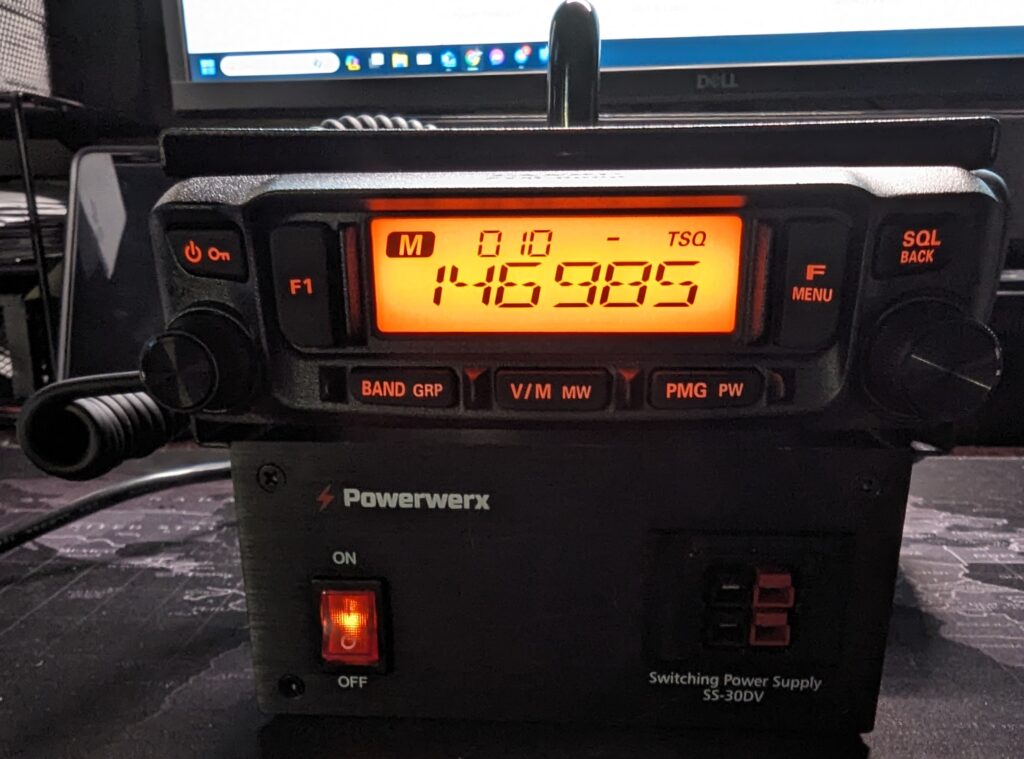
I decided to build a small 50W VHF/UHF station to use for portable operations, such as supporting events or setting up in a temporary location, with a choice of using AC power or a battery. I don’t need anything fancy like DMR or D-Star, but I might want to to use it for APRS or WinLink.
After a bit of research and pricing options, I went with something that turned out to be a very easy build. I chose a Yaesu FTM-6000R as the transceiver. It has basic features, but has gotten some good reviews. It is also known to be a good transceiver for data, and is 9600 bps capable.
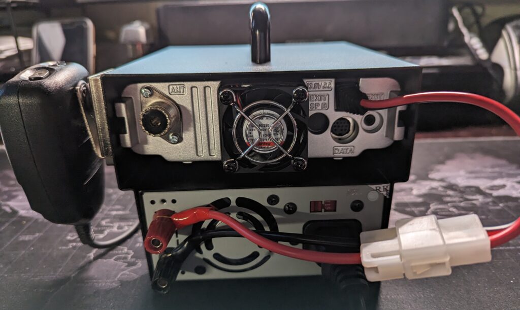
I also chose a 30 amp switching power supply and a mobile base station enclosure from PowerWerx, to make it a single unit that’s easy to carry around. The enclosure includes a short DC cable to connect the radio to the power supply. If I want to use a battery instead of the power supply, I just disconnect the T-connector from the power supply, and connect it to the battery. It was very easy to assemble the whole system.
I tested with the power supply and with a battery, and it works great. The whole unit is very compact and stable.
My next step will be to configure it for WinLink and APRS. I have a Mobilinkd TNC-4, and I ordered a DigiRig. The FTM-6000R has a 10 pin MiniDin connector, and DigiRig sells 1200 bps and 9600 bps cables for the radio. DigiRig also sells an adapter cable to use DigiRig cables with a Mobilinkd, and vice versa.
I’ll make another post after testing the setup with WinLink and APRS.
I’m working on some significant upgrades to my ham radio station. I finally received a Mercury IIIs amplifier. I was on the waiting list for about a year. I also got a Palstar HF Auto tuner to handle the increased power from the amp. For outside the shack I also got a K4KIO Hexbeam antenna. The only problem is that I don’t have a tower for it yet. That will be next, and hopefully soon! I’ll make additional posts as I bring the new equipment online.
It has been a year since I posted a new item! Time to get back to it! My last post was about a project for my IC-705 using an M5Stack microcontroller. I became interested in learning about other ham radio related projects using microcontrollers.
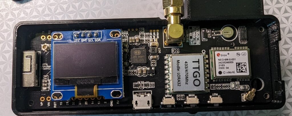
Searching online, I found two related projects to build an APRS iGate and a tracker. Both of these projects use inexpensive LoRa32 microcontroller boards. I chose TTGO T-Beam v1.1 boards that operate on 433 MHz. Make sure you buy the 433 MHz version of the board for the APRS projects. The board includes a small OLED screen, and has onboard WiFi, GPS and SMA connector for the antenna. You will probably have to solder the OLED screen to the board, but there are only four pins to solder.
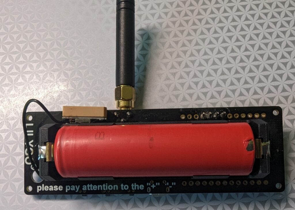
On the back of the board, there is a battery holder for an 18650 3.7 V lithium ion battery to power the board. The board can also be powered through the microUSB port, which also recharges the battery. There are other similar LoRa32 boards that you can use for these projects, and they are readily available on Amazon, eBay, and other online retailers.
Front and back of TTGO T-Beam v1.1 ESP32 433MHz LoRa32 board
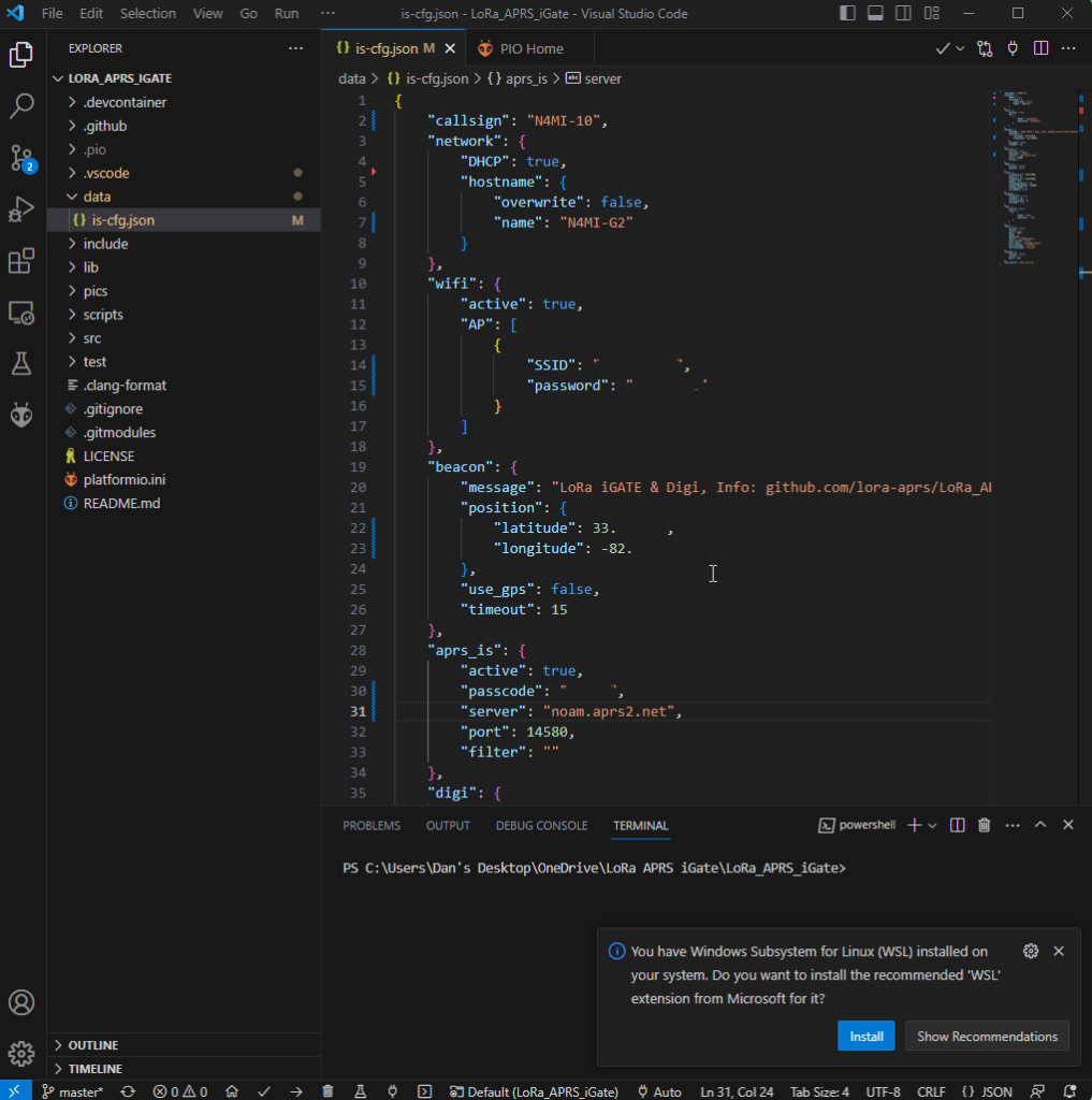
Programming the board is fairly easy. The iGate and tracker project pages on GitHub include links to quick start guides. The quick start guides are in German and French, but you can right-click in Chrome and choose “Translate to English”. Even better, there is an excellent video by Tech Minds on YouTube that will take you step-by-step through the process of configuring and programming the iGate and tracker modules using Visual Studio Code with the PlatformIO plugin. This process will load the firmware onto the module, as well as a json configuration file that includes your callsign, wifi info (for the iGate), etc. I highly recommend viewing the Tech Minds video before you start these projects!
Lora APRS iGate json configuration file in Visual Studio Code
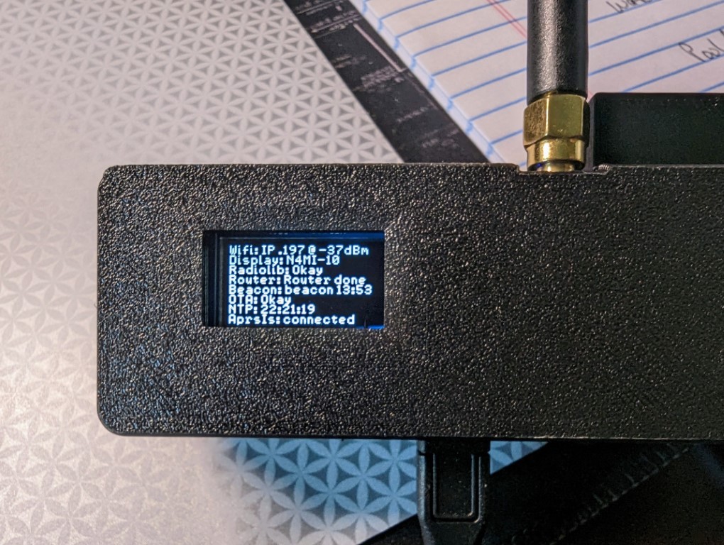
After programming the iGate and tracker, I was ready to test! I missed a step in my initial configuration of the iGate, so it did not connect to my home wifi on the first attempt. Once that was fixed, it connected to the internate and I was able to see the LoRa iGate symbol for my ssid N4MI-10 appear on the aprs.fi live APRS map. The iGate is operating on 433.775 MHz.
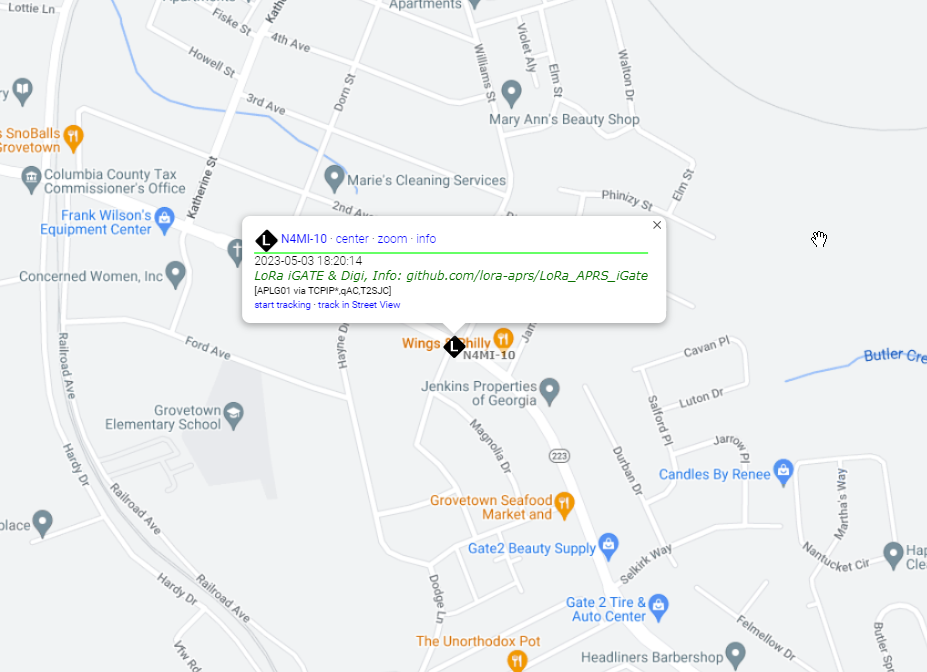
OLED screen showing LoRa APRS iGate configurationN4MI-10 LoRa APRS iGate, operating on 433.775 MHz, displayed on aprs.fi
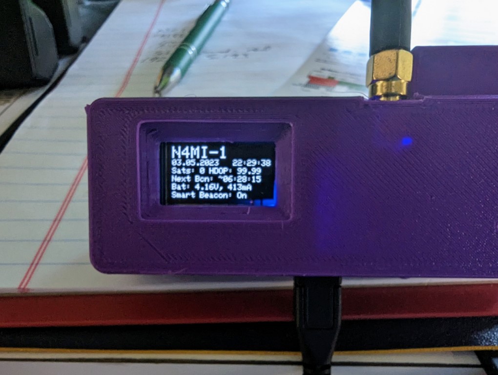
Once the iGate was operational, it was time to test the tracker. I chose N4MI-1 as the ssid for testing the tracker. I have some other APRS capable radios, so I will have to come up with a plan for assigning a ssid for each of them. The tracker powered up and initialized. Once it acquired enough satellites for a fix, I saw it transmit the first beacon, which was immediately picked up by the iGate. Awesome!
You can configure the tracker for smart beaconing in the json configuration file. You can also manually transmit a beacon using the middle button on the LoRa module.
OLED screen on LoRa 433 MHz APRS tracker
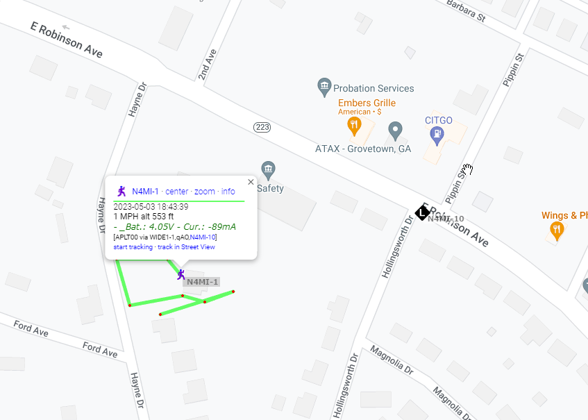
I took the tracker out for a short walk, and transmitted a beacon from several locations, all of which were received by the iGate and displayed on aprs.fi.
Positions from N4MI-1 LoRa 433 MHz APRS tracker displayed on aprs.fi
The transmitter in the LoRa board is very low power, about 200 mW, so the range with the small SMA antenna is limited. The range can be extended by using a better antenna at a higher elevation. Additionally, a small RF amplifier could be used to increase the power.
This was a very fun and relatively easy project. I am planning to attach a 70cm antenna at a higher elevation to the iGate in case other hams in this area would like to build and use LoRa 433 MHz APRS trackers.
The Icom IC-705 is an amazing QRP transceiver with lots of advanced features. Those features include built-in Bluetooth and wireless LAN, creating opportunity for display and control the IC-705 remotely. Some excellent free software recently became available to take advantage of the Bluetooth capability for a remote display using an inexpensive IoT development board. Also, an incredible iPad app was recently released that allows full remote display and control of the IC-705 via WiFi or LAN.
Remote S Meter and MultiMeter Projects with M5Stack
There are two very easy projects using code available on GitHub and an inexpensive M5Stack Core Development Kit: one to create a remote S Meter and another to create a more advanced and very useful remote MultiMeter.
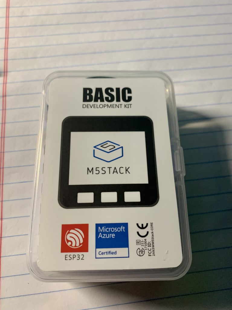
M5Stack Core Development Kit
The M5Stack is an ESP32 development system for IoT applications. This extremely powerful yet low-cost chip includes Wi-Fi and Bluetooth and has quickly become popular over the past year or so. The M5Stack Core Development Kit is currently available on Amazon for about $50.
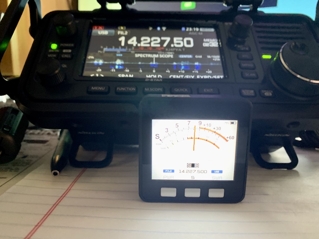
The first project I completed using the M5Stack was the IC705SMeter, created by Armel, F4HWN. Once the code is installed and the M5Stack is connected by Bluetooth to the IC-705, it has a selectable display of the received signal strength, output power, and SWR. It also displays the current frequency, mode and filter. It was very easy to install the software and connect to the IC-705 by following step by step instructions in a YouTube video by Ham Radio Dude.
Remote S-Meter connected to IC-705 via Bluetooth
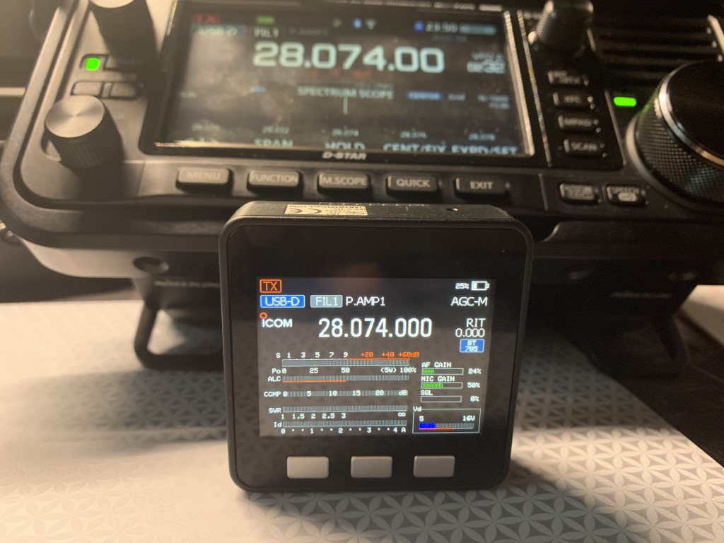
There is also another more advanced remote meter project, also created by Armel, called the ICMultiMeter. This project allows you to display the equivalent of the meter screen of the IC-705 on the M5Stack screen, which allows you to dedicate the IC-705’s screen to the waterfall while seeing all the signal measurements simultaneously on the M5Stack screen. The installation process is very similar to the S Meter project. A YouTube video by Tech Minds has easy-to-follow instructions to build and install the remote MultiMeter.
IC MultiMeter connected to the IC-705 via Bluetooth
SDR Control Software for iPad
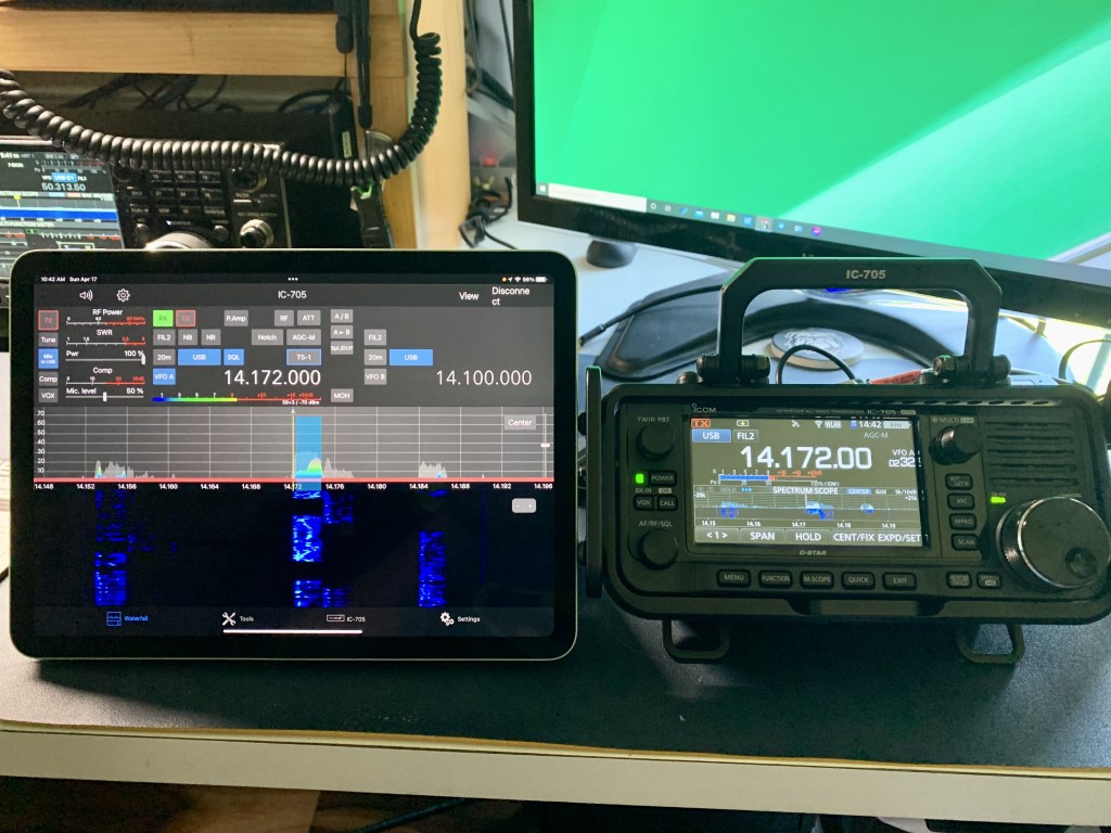
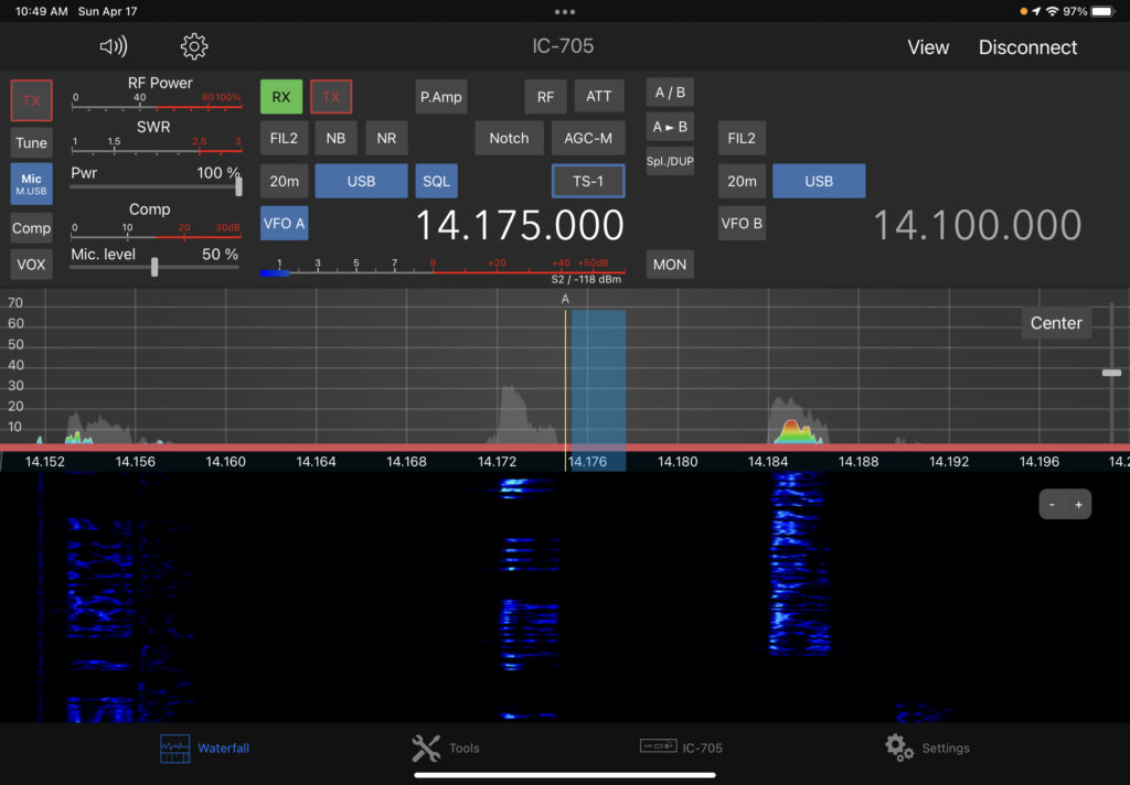
Having a remote meter is wonderful, but what if you’d like to have a full remote display and control of the IC-705? An application recently released for iPad will do just that. SDR-Control for Icom, available on the App Store, allows remote operation of the IC-705 without additional hardware or software. The app costs $50, but has tons of features, to include an integrated logbook, CW keyer and FT8/FT4 tool. An important caveat is that the IC-705 and iPad must be connected to the same WiFi network. The app will also control IC-7610 and IC-9700 transceivers connected to the same network via LAN. A YouTube video by Tech Minds provides an excellent overview of the SDR-Control app.
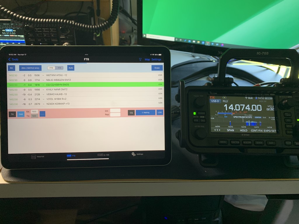
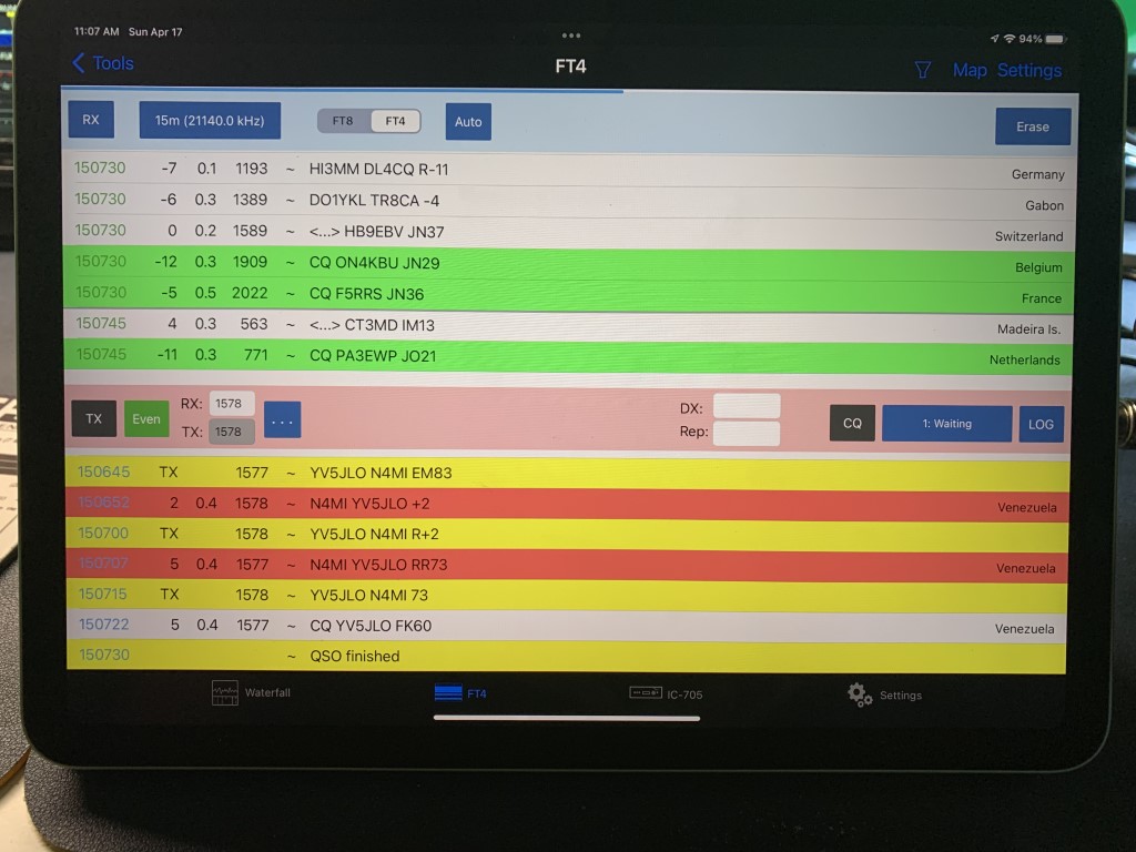
Once installed on the iPad, the app includes an integrated instruction manual explaining all of the functions, to include connecting the app to the IC-705. There is also an online version of the instruction manual. Following the instructions in the manual, I was able to connect to the IC-705 in just a few minutes. I found the app to be very easy to understand and use. When using the integrated FT8/FT4 tool, I did have to consult the manual to adjust the signal levels. Once that was done, it worked very well. The FT8/FT4 tool does not have all of the functionality of WSJT-X (no DXpedition mode), but it works well for casual operating. So far I have only used the app with the IC-705. I don’t yet have my IC-7610 or IC-9700 connected to my home network, but I plan to do that soon so that I can control the transceivers from anywhere in the house.
SDR-Control app connected to the IC-705 via WiFiScreen shot of the SDR-Control appIntegrated FT8/FT4 tool in SDR-ControlI made several FT8 contacts using the integrated FT8/FT4 functions in the appWaterfall screen on the SDR-Control app showing stations sending FT8 signals
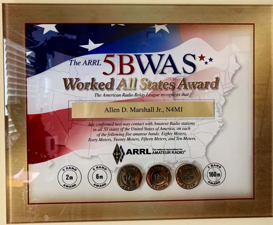
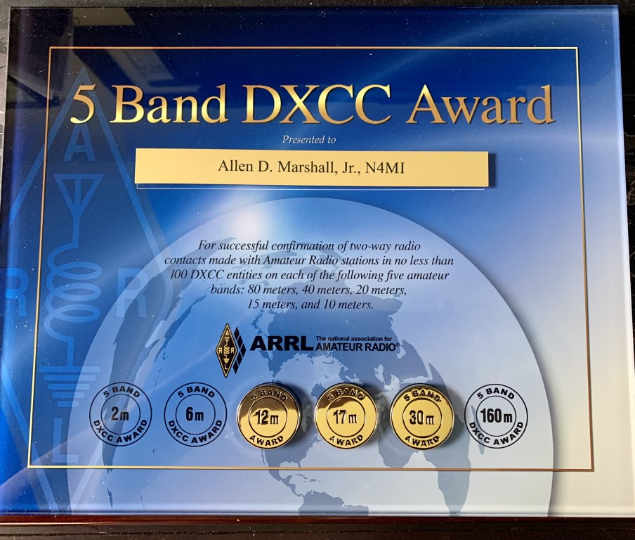
Ever since I got my ham radio license, just over 6 years ago, I have been interesting in DXing, contesting, and awards. I started out at the bottom of a solar cycle, which helped me learn how to make contacts under less than ideal conditions. I’m not as much into the competition with other hams, but it’s satisfying to set and achieve my own personal goals. Now that band conditions are starting to become more favorable, I was recently able to achieve two longtime goals, which are the 5 Band Works All States (WAS) and 5 Band DXCC awards.
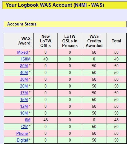
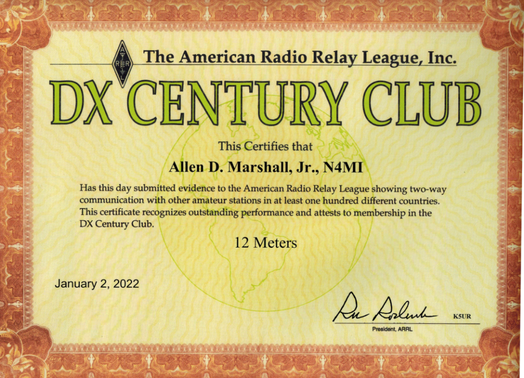
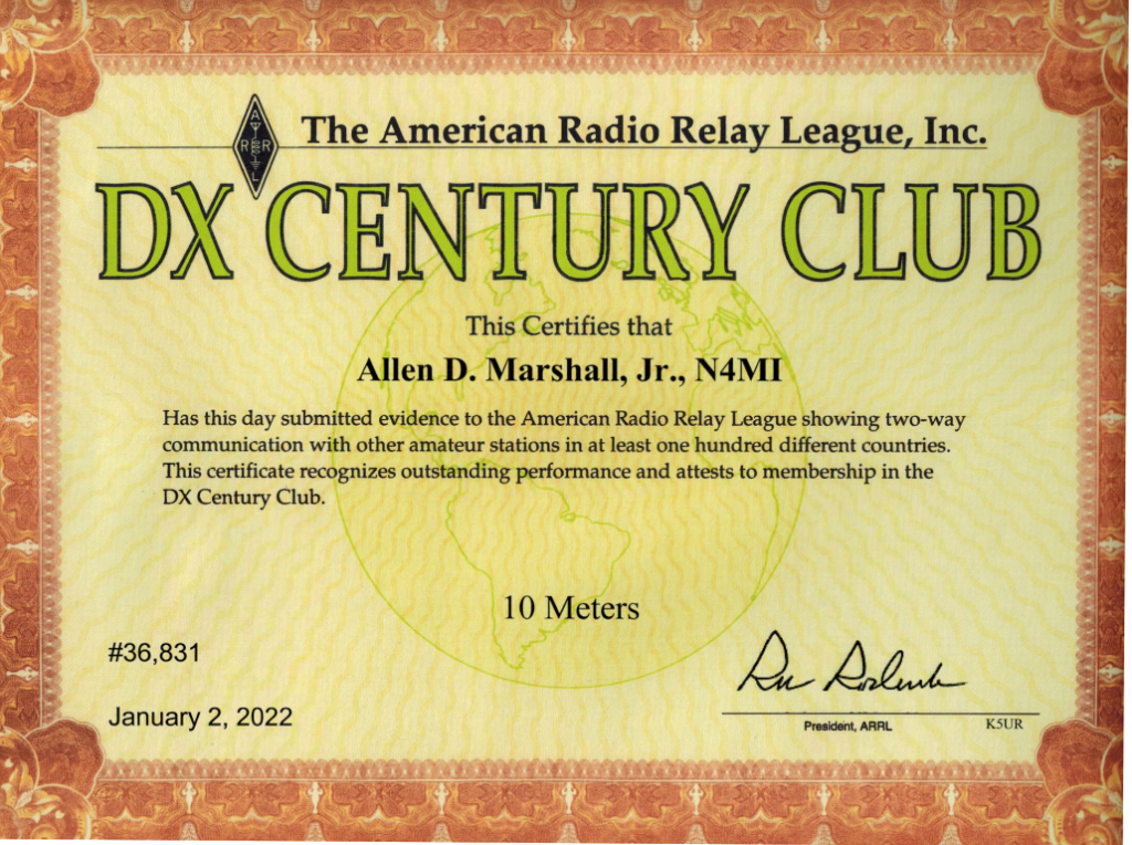
The last band I needed for both WAS and DXCC was 10 meters. The band conditions improved enough over the past few months to make that possible. I was also able to add endorsements for 30 meters, 17 meters and 12 meters. I still need Alaska and Hawaii for WAS on 6 meters, and Hawaii for WAS on 160 meters. Maybe someday!
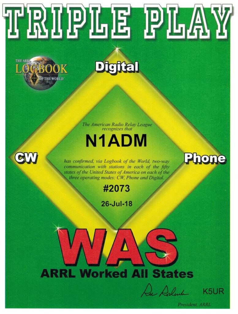
I was able to complete the Triple Play WAS award a few years ago.
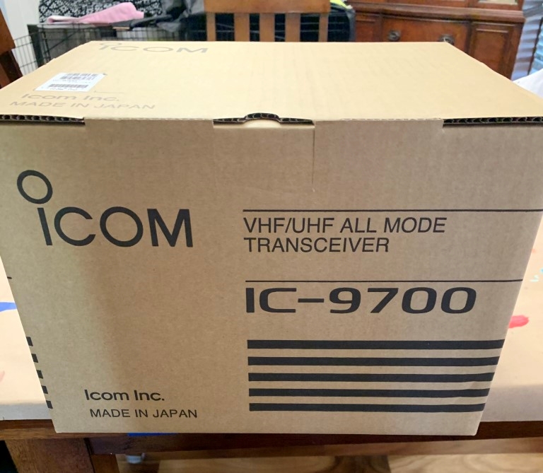
After a long wait, I finally added an Icom IC-9700 to improve the VHF and UHF capability in my shack. I decided to place an order in late December, but all of the ham radio dealers were out of stock at the time. I placed the order, and the dealer estimated delivery in February. That later slipped to March, and then to April. This morning, April 3rd, it finally arrived!
Ready for unboxing!It took about a half hour to get the radio connected and in place.
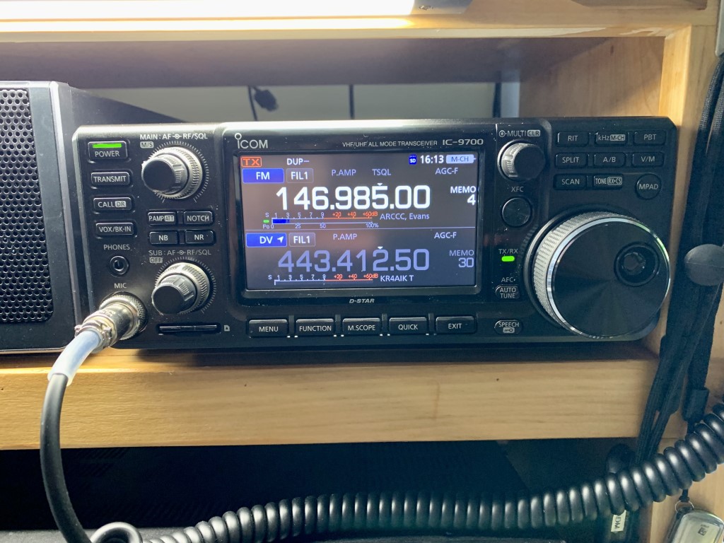
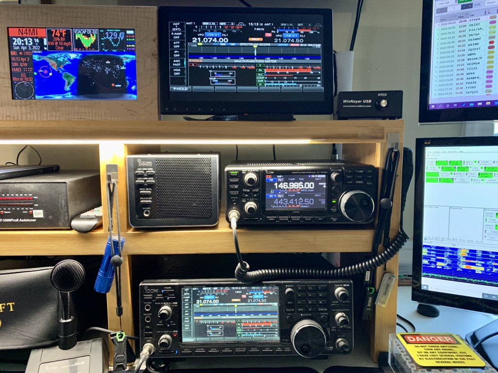
Initial setup was fairly easy, since I already had the power cable, USB cable, ground wire, and coax routed to the spot on my desk for the IC-9700. Since my current VHF/UHF antenna is a Diamond X500HA for 2M and 70cm, I will not get to use the 23cm right away. I used a Diamond MX-72N duplexer, because the IC-9700 has separate 2M and 70cm connectors.
A very nice addition to the shack!
To make programming the radio a little bit easier, I purchased RTSystems WC-9700 software. I use RTSystems programmers for all of my other radios, and it saves a lot of time and effort. The D-Star Calc feature makes adding D-Star repeaters and reflectors a breeze.
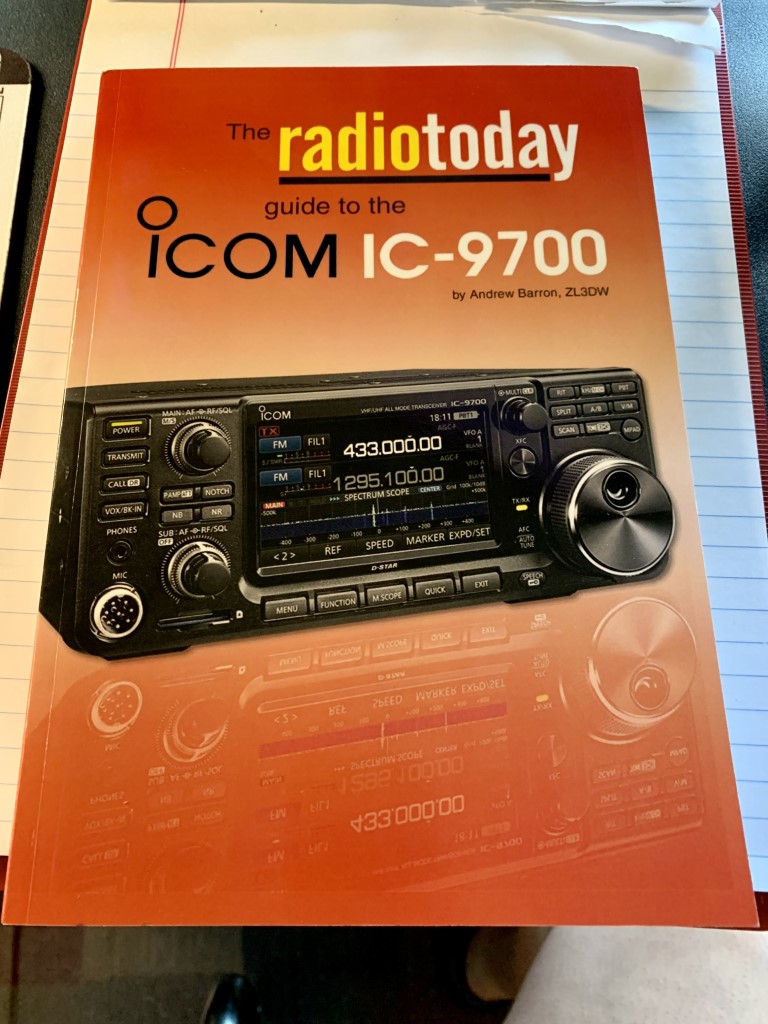
The IC-9700 has lots more features and settings than any of the other VHF/UHF transceivers I used. Even though I am very familiar with the Icom interface and controls, it’s clear that I will have a learning curve to get the best out of this radio. To help with setting up and learning the many features of the radio, I also got a copy of the Radio Today Guide to the IC-9700, by Andrew Barron, ZL3DW. I also have his guides for the IC-7300, IC-7610, and IC-705.
If you buy one of the new Icom transceivers, get this book!
I’m looking forward to seeing what this radio can do. I am going to try out using digital modes on VHF and UHF. My long-term plans include getting a new triband (2M, 70cm, 23cm) antenna to take full advantage of all three bands. I am also considering adding additional antennas to work amateur radio satellites.
Last month, I was given the opportunity to participate in a 30-day test and review of the Bilal Isotron 40M antenna for the 100 Watts and a Wire podcast. The Isotron is a strange looking and compact antenna that has reviews with an overall rating of 4 stars on eham.net. After building and then testing the antenna for a month, I was invited to participate in the podcast along with two other hams to give our review of the antenna for the following criteria:
You can listen to the podcast here. In addition to the audio podcast, there are videos covering each of the review criteria on the 100 Watts and a Wire YouTube channel. (Each of the criteria listed above includes a link to the YouTube video for that topic.)
Assembling the Antenna
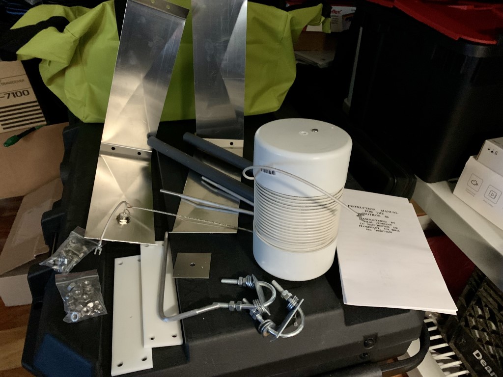
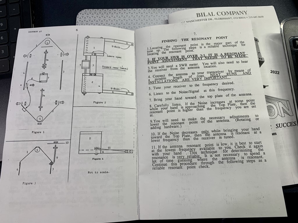
The antenna arrived in a sturdy box, and all of the parts were in good shape. The paper manual is adequate and includes diagrams that were helpful for assembly. It took me about an hour to put it together. Once assembled and tightened, it is a sturdy antenna. It’s worth reading the manual closely before attempting assembly, and again afterwards to understand the instructions for tuning the SWR.
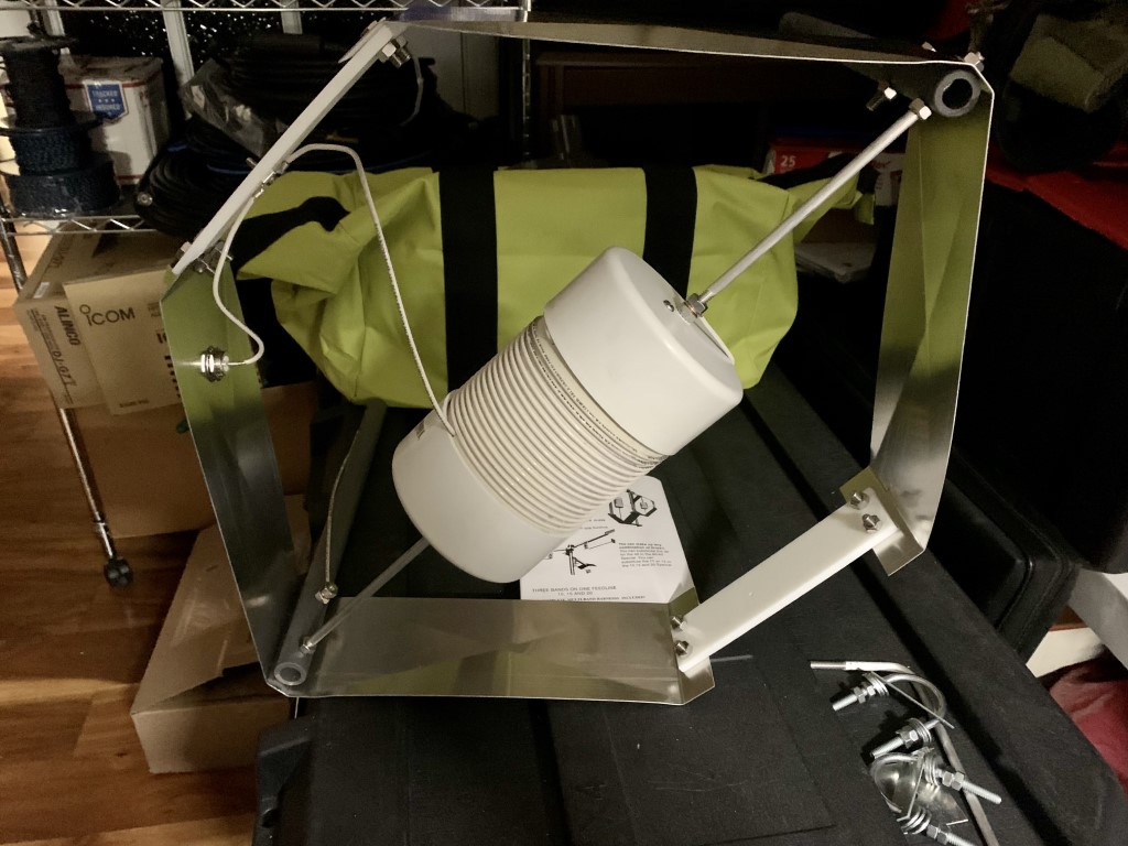
Photo of all parts prior to assembling the antennaThe manual is not fancy, but includes good instructions to assemble the antenna. Pay close attention to the instructions for tuning the antenna.The antenna is almost fully assembled, with the U-bolts for the mast and tuning arm still to be installed.
Installing and Testing the Antenna
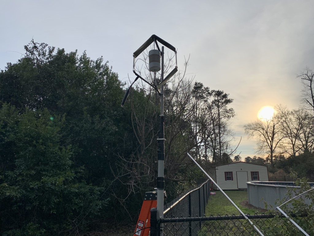
I installed the antenna on 28-foot heavy duty fiberglass telescoping mast from Max Gain Systems. The mast is located next to a long chain link fence, which may have interacted with the antenna and made tuning it a bit challenging initially. Once attached to the mast, I used a Comet antenna analyzer, and attempted to tune the antenna for the lower end of 40 meters for CW and digital modes. For my first test, with the antenna mast lowered, the SWR was just above 3:1. I believe that was partially due to close proximity of the metal fence. Also, the manual specifies that the antenna works best with a metal mast, likely to serve as a counterpoise. I attached about 25 feet of copper wire to the antenna ground as a counterpoise, and made some more tuning adjustments. After that, and when I raised the antenna to 25 feet, the SWR was down to 1.6:1. Close enough, since I have an antenna tuner in the shack.
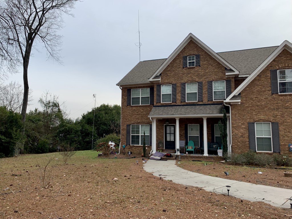
I mounted the antenna on a HD fiberglass telescoping mast. The mast was lowered to mount and tune the antenna. This picture shows a HF choke at the feed point, which I ended up removing after testing.The mast extended with the antenna about 25 feet off the ground.From a distance, the antenna is not quite as noticeable as the roof-mounted VHF/UHF vertical and 6M horizontal loop antennas.
Performance
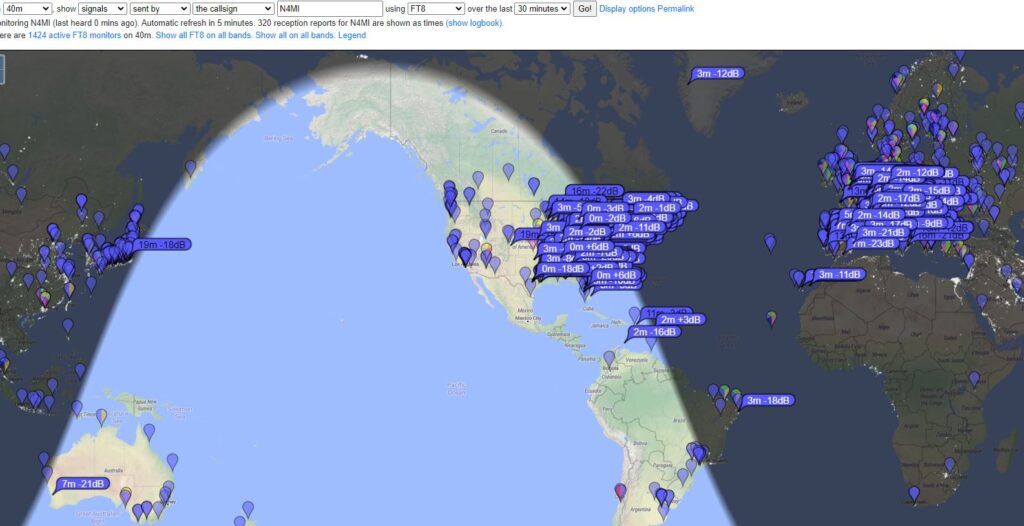
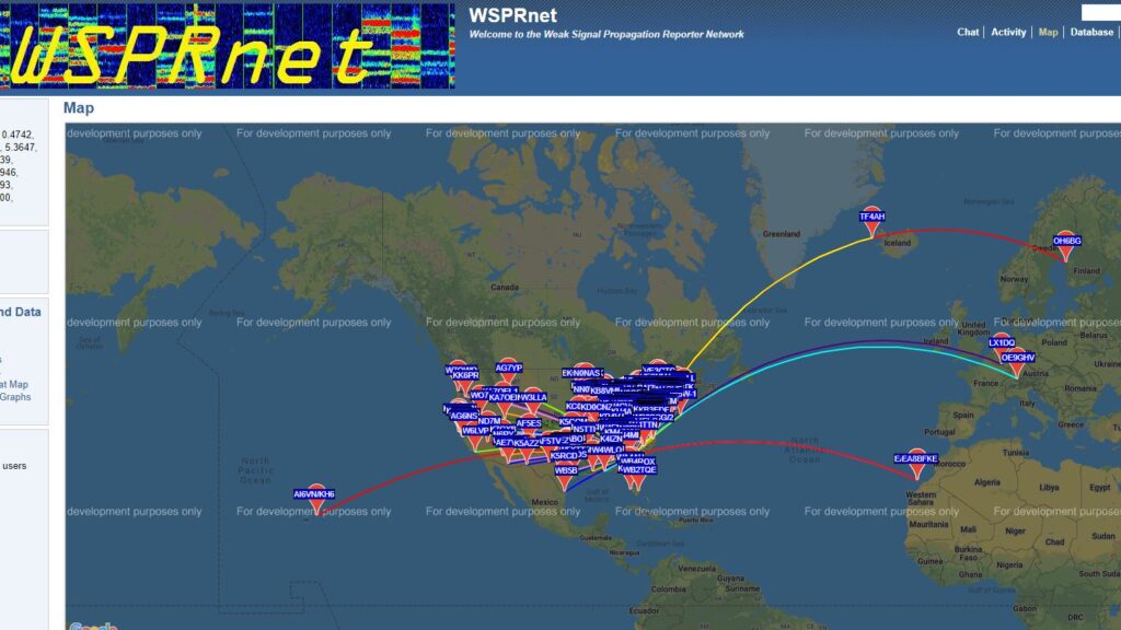
I tested the antenna for 30 days using FT8, WSPR, CW and SSB. The first contact I made on FT8 was in Washington State… a very promising start! Using FT8, I was easily able to work stations all over North America, as well as some DX stations in Europe, Australia and Japan. I also tested the antenna using WSPR for 24 hours, and my signals were received across North America and in Europe. I used the antenna for all of my 40 meter phone and CW contacts during Winter Field Day, and I was able to make a lot of contacts across the U.S. and Canada. The antenna performs better than I expected it would. However, it is not a good for receiving when compared against my end-fed halfwave antenna. I made comparisons several days, and the wire antenna was always noticeably better for receiving.
Stations receiving FT8 signals from Isotron 40M antenna on January 19th, 202224 hour WSPR test with Isotron 40M antennaCompleted QSOs made with the Isotron 40M antenna as of January 20th, 2022
Final Thoughts
Pros: 1. It actually works! When I first looked at the antenna, I was skeptical. After testing it for 30 days, I realize there are some use cases where this antenna is a good choice. 2. This antenna would probably good for someone with HOA restrictions, as it is small enough to be hidden. However, keep in mind that my testing was with the antenna mounted at 25 feet and in the clear. 3. Because the antenna is compact and can be raised quickly, it would also be a good choice for portable operations or emergency communications. Cons: 1. The antenna is only for the 40 meter band. If you have space for several antennas, that’s probably not an issue. 2. The antenna can be somewhat finicky with SWR. It made several trips up and down a ladder, and lowered the mast a few times, to get it adjusted. I also had to retune the antenna after one particularly cold, windy, rainy day.
The antenna retails for $160. Would I have bought this antenna on my own? Probably not. During the podcast, each reviewer was asked to give a “signal report” between 55 and 59 as an overall rating of the antenna. My report was solidly in the middle with a 57. It is definitely strange looking, but the appearance and compact size belie an antenna that actually performs fairly well, as long as you don’t expect miracles. I will most likely take the antenna down from the mast to install an off-center-fed dipole, and see if one of my ham friends living in a HOA community would like to give the Isotron a try.
This was a great ham radio experience for me. I had a lot of fun building, testing and using the antenna. I also enjoyed being included on the 100 Watts and a Wire podcast, and Christian Cudnick, K0STH, is a great host.
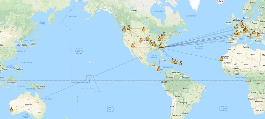
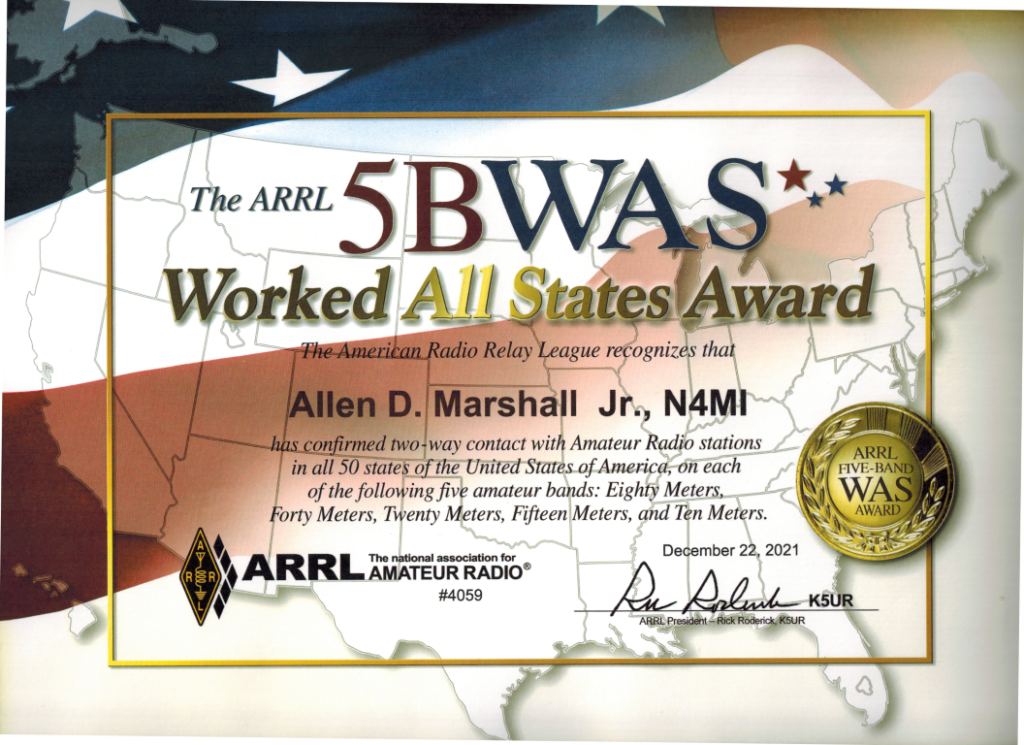
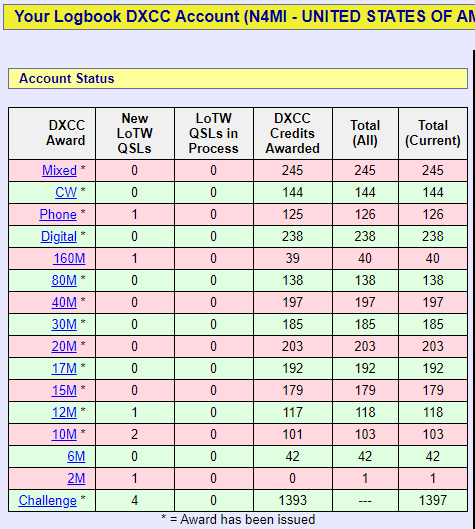
The conditions on 10 meters have finally become favorable for me to get enough confirmations to complete WAS and DXCC on that band, and those were also what I needed to complete 5BWAS and 5BDXCC. I received the 5BWAS certificate, and applied for the 5BDXCC certificate. I also have WAS and DXCC on 30M, 17M and 12M. All of these were completed using 100 watts and omnidirectional antennas. The key has been persistence, and some luck to be on the radio when the bands are open.
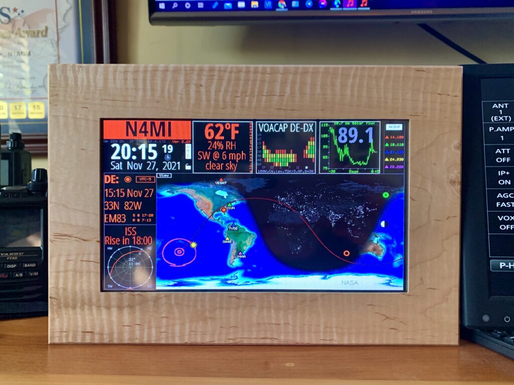
I purchased a Veritium HFClock as an impulse buy when I saw it on sale in an email from Gigaparts. I tried to build a HamClock using a Raspberry Pi and 7″ touchscreen, but I could never quite get it to work correctly. The Veritium HFClock is far more expensive, but it has a 9″ touchscreen in an attractive hardwood frame, and was easy to configure right out of the box. It’s definitely an attractive and informative station accessory. I may try again to build a HFClock with a Raspberry Pi someday.